
Canter chipper head

a chipper head and canter technology, applied in the field of canter chipper heads, can solve the problems of inconsistency in single cutting assembly of the chipper head, and significant amount of stress, so as to reduce the cutting force, improve the quality of chips being produced, and improve the quality of chips.

Inactive Publication Date: 2005-08-02
EQUIP HYDAULIQUE BOREAL
View PDF25 Cites 6 Cited by
  • Summary
  • Abstract
  • Description
  • Claims
  • Application Information

AI Technical Summary

Benefits of technology

[0007]This dual step cutting operation is advantageous for a number of reasons, namely it provides a lumber with a surface having a superior finish, reduction of vibrations while the head is performing the cutting and a reduction of the cutting force.

Problems solved by technology

A deficiency with many canter chipper heads, such as the one described in Canadian Patent 2,314,718, is that the chipper head has only a single cutting assembly for performing both the chip cutting and the finishing of the piece of lumber.
This puts a significant amount of stress on the blades of the cutting assembly, which results in an inconsistency in the quality of the chips being produced, and a shorter life span for the cutting assembly.

Method used


Image

  • Canter chipper head
  • Canter chipper head
  • Canter chipper head

Examples


Embodiment Construction

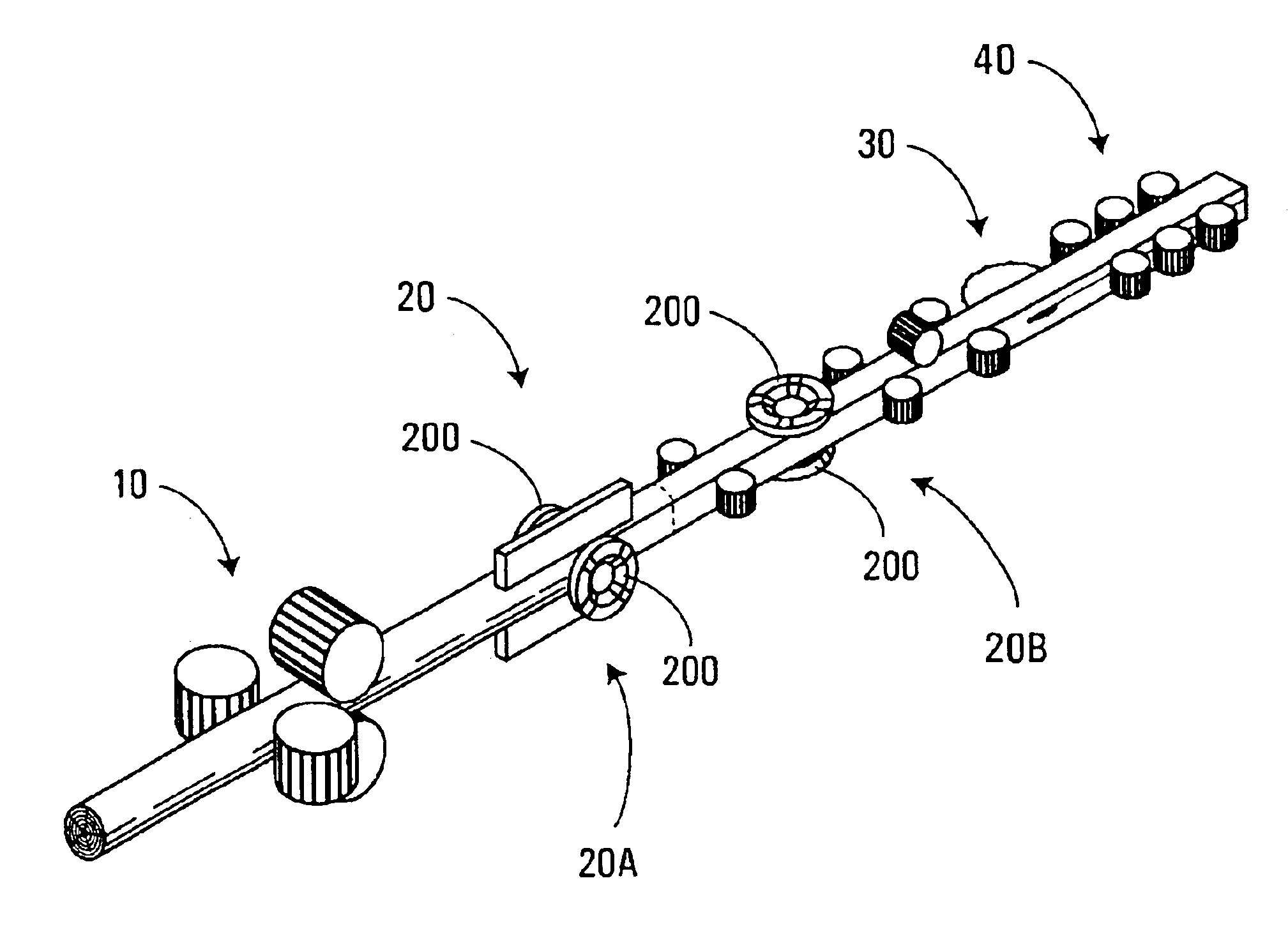
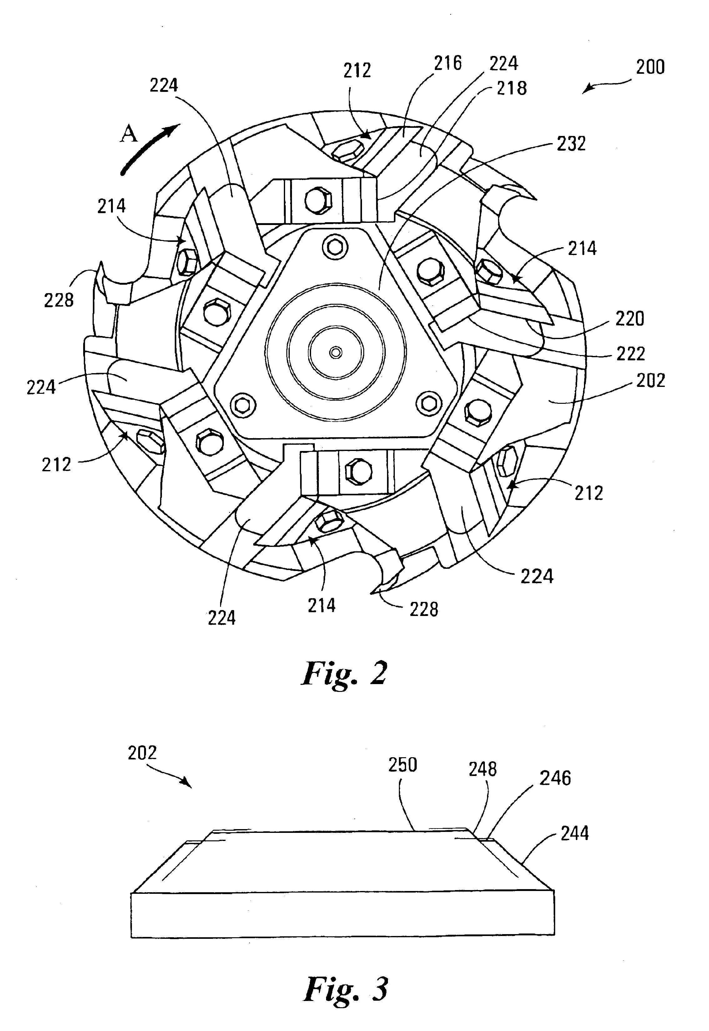
[0029]The present invention relates to a canter chipper head for use in a compact sawmill, similar to that shown in FIG. 1. A typical compact sawmill, such as the one shown in FIG. 1, comprises the following processing and handling components:[0030]a) An in-feed section 10 in which there is a first and a second pair of large diameter power driven feed rolls for propelling a log endwise along a pre-selected feed path;[0031]b) A canting section 20 in which there is a first and a second pair of canter chipper heads 200, which will be described in detail further on in the specification, and which are offset 90 degrees from one another about the axis of the feed path;[0032]c) A timber sub-dividing or sawing section 30; and[0033]d) A lumber out-feed conveyor section 40 made up of a plurality of small diameter power driven feed rolls for engaging the flat faces of a squared timber piece to guide and propel it along the pre-selected feed path.

[0034]The canting section 20 has a first canting...


PUM


Abstract

The present invention provides a canter chipper head that comprises a rotor suitable for rotation about a rotation axis. The rotor has a lateral side and a frontal side, and includes a first cutting assembly and a second cutting assembly that are each mounted to the rotor. During rotation, the first cutting assembly defines a first lateral cutting surface around the rotation axis, and a first frontal cutting surface that is generally transverse to the rotation axis. The first lateral cutting surface and the first frontal cutting surface perform a primary cut in a log. The second cutting assembly defines a second lateral cutting surface around the rotation axis, and a second frontal cutting surface that is generally transverse to the rotation axis. The second lateral cutting surface and the second frontal cutting surface perform a secondary cut in the log that is deeper than the primary cut.

Description

FIELD OF THE INVENTION[0001]The present invention relates to canter chipper heads used for producing chips and square pieces of lumber from a log. More particularly, the present invention relates to canter chipper heads having improved cutting and finishing cutting surfaces.BACKGROUND OF THE INVENTION[0002]Canter chipper heads for processing logs in order to produce wood chips and square pieces of lumber are known in the art. An example of such a canter chipper head can be seen in Canadian Patent 2,314,718 issued on Aug. 21, 2001 to Pelletier et al.[0003]Chips that are produced from canter chipper heads have many uses. Therefore, when forming wood chips it is required that the chips are of a certain consistency and quality. There are a number of factors involved in the production of quality chips, one such factor is the canter chipper head design and more specifically, the cutting surface design of the head.[0004]A deficiency with many canter chipper heads, such as the one described...

Claims


Application Information

Patent Timeline
Patent Type & Authority Patents(United States)
IPC IPC(8): B27L11/00
CPCB27L11/005B27L11/007Y10T407/1962Y10T407/1924Y10T407/196
Inventor ROBITAILLE, PASCAL
Owner EQUIP HYDAULIQUE BOREAL
Learn More