End-fitting for flexible pipe

Inactive Publication Date: 2005-08-02
COFLEXIP
View PDF22 Cites 74 Cited by
  • Summary
  • Abstract
  • Description
  • Claims
  • Application Information

AI Technical Summary

Benefits of technology

[0019]Advantageously, the rear deformable ring forms part of a bicone possessing, at the front, another deformable ring intended also to sink into the intermediate sheath. The bicone has a radial orifice for testing the sealing between the two deformable rings of the bicone. Preferably, an O-ring seal is also provided between the flange and the stepped part in order to prevent leaks during the sealing test. By virtue of these arrangements, it is easy to first crimp the intermediate sheath a

Problems solved by technology

However, these documents do not relate to pipes provided with an intermediate sheath that also has to be crimped to seal it.
This construction is generally satisfactory, but it turns out in use that the manufacture is not simple, since many very precise contact adjustments have to be made on the stepped part, the mounting of which is no

Method used


Image

  • End-fitting for flexible pipe
  • End-fitting for flexible pipe
  • End-fitting for flexible pipe

Examples


Embodiment Construction

[0022]Other advantages and features will become apparent on reading the description that follows, with reference to the appended schematic drawings in which:

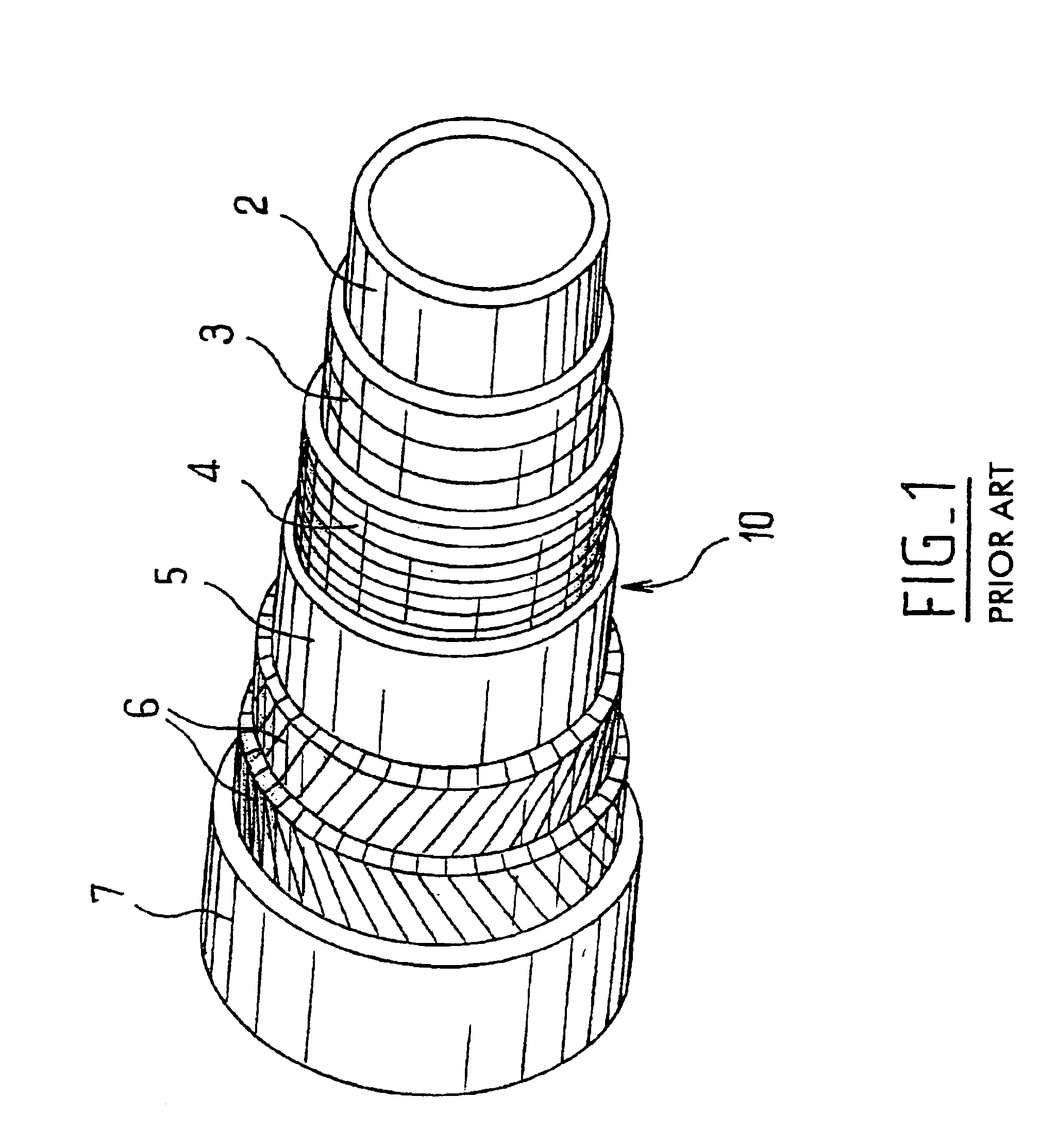
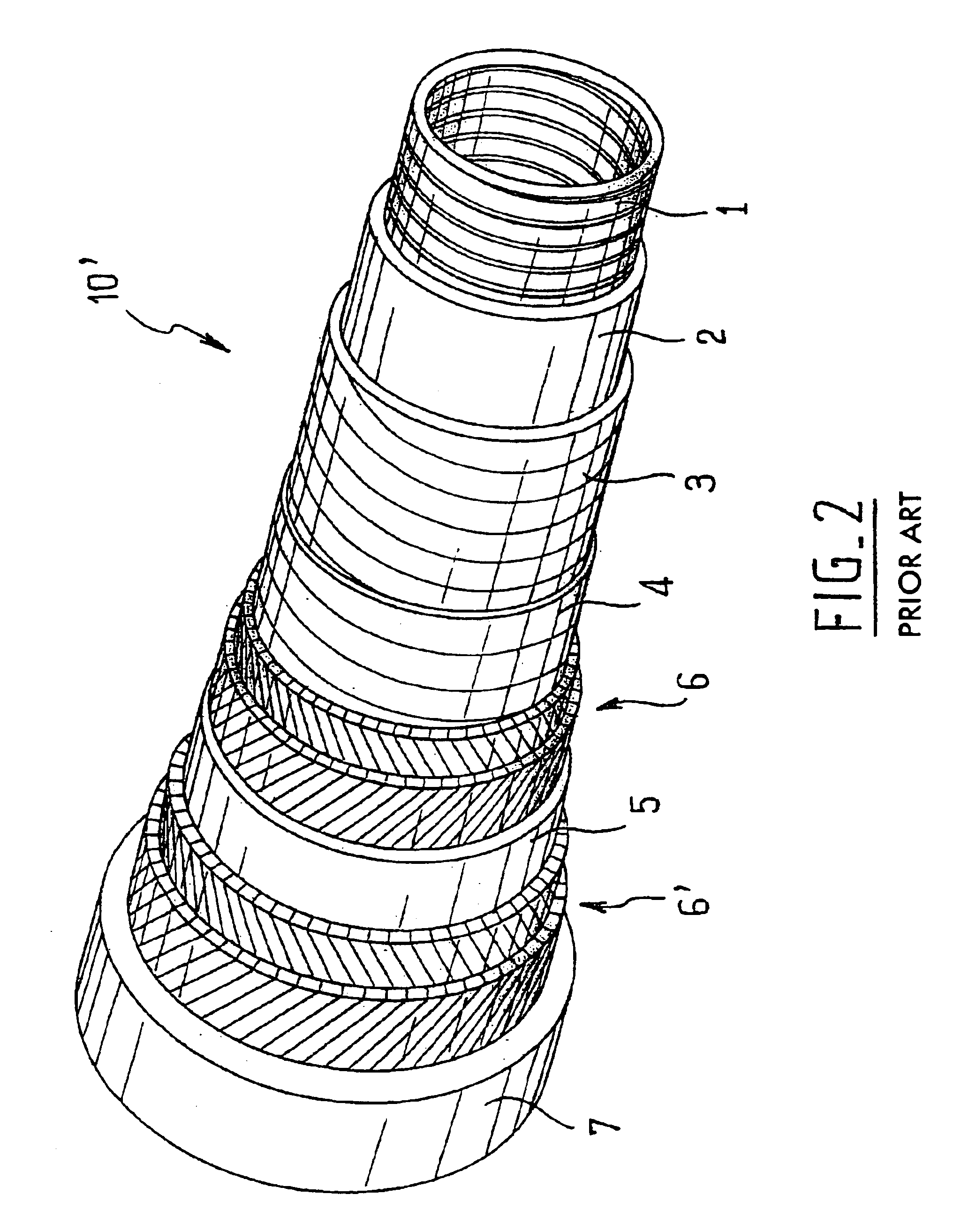
[0023]FIGS. 1 and 2 are perspective views of a smooth-bore pipe and a rough-bore pipe, respectively, to which the invention may apply;

[0024]FIG. 3 is a longitudinal sectional view of an end-fitting already developed by the Applicant; and

[0025]FIGS. 4 and 5 are longitudinal sectional view s of an end-fitting according to the invention, at an intermediate stage of assembly and at the final stage, respectively.

DESCRIPTION OF THE PREFERRED EMBODIMENTS

[0026]The smooth-bore pipe 10 of FIG. 1 comprises, from the inside outward, a polymeric internal sealing sheath 2, a metal vault 3, consisting of the short-pitch helical winding of at least one metal profile wire (for example a self-interlocked zeta wire), if necessary a hoop reinforcement 4, formed by a short-pitch winding of rectangular wire, an anti-collapse intermediate sheath 5, ar...


PUM

PropertyMeasurementUnit
Pressureaaaaaaaaaa

Abstract

A fixing end-fitting for a flexible tubular pipe, the pipe comprising an inner sealing sheath, a pressure vault comprising a short-pitch helical winding of a metal forming wire, an intermediate sheath and at least a web of tensile long-pitch wound armour wires and an outer sealing sheath. The end-fitting comprises a stepped part capable of sliding into a stepped cylindrical housing of the end-fitting. Two crimping elements sealingly fix the inner sheath and the intermediate sheath. Screws enable the stepped part to be brought closer to and be fixed on the end-fitting. The stepped part and the deformable elements constitute three separate elements, thereby facilitating mounting and providing a better control of tightness.

Description

BACKGROUND OF THE INVENTION[0001]The present invention relates to an end-fitting for a flexible pipe for transporting, over long distances, a fluid which is under pressure and possibly at a high temperature, such as a gas, oil, water or other fluids. The invention relates most particularly to an end-fitting for a pipe intended for offshore oil operations.[0002]The flexible pipes used offshore must be able to resist high internal pressures and / or external pressures and also withstand longitudinal bending or twisting without the risk of being ruptured.[0003]They have various configurations depending on their precise use but in general they satisfy the constructional criteria defined in particular in the recommendations API 17 B and API 17 J drawn up by the American Petroleum Institute under the title “Recommended Practice for Flexible Pipe” and “Specification for Unbonded Flexible Pipe”.[0004]A flexible pipe generally comprises, from the inside outwards:[0005]an internal sealing sheat...

Claims


Application Information

Patent Timeline
IPC IPC(8): F16L33/00F16L33/01
CPCF16L33/003F16L33/01F16L11/083
Inventor BUON, ERICBERTON, HUGUES
Owner COFLEXIP
Why Eureka
Try Eureka