Phase change ink imaging component with nano-size filler
a phase change ink and filler technology, applied in the field of imaging components with nano-size fillers, can solve the problems of increasing printer weight and cost, insufficient soft and tacky ink to adhere to the print medium, and needing a fairly complex two-layer pressure roller
- Summary
- Abstract
- Description
- Claims
- Application Information
AI Technical Summary
Problems solved by technology
Method used
Image
Examples
example 1
Preparation of Nano-Sized Filled Fluoroelastomer Imaging Member Outer Layer
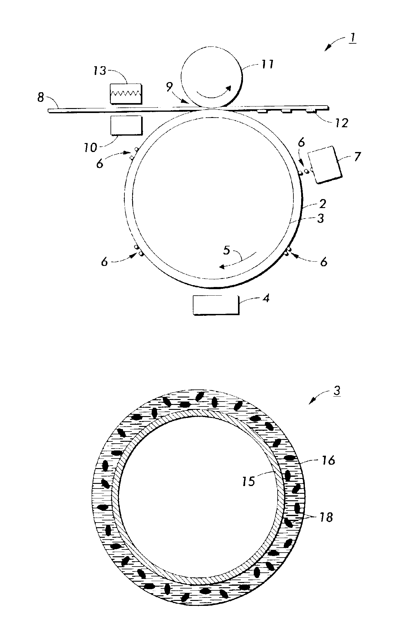
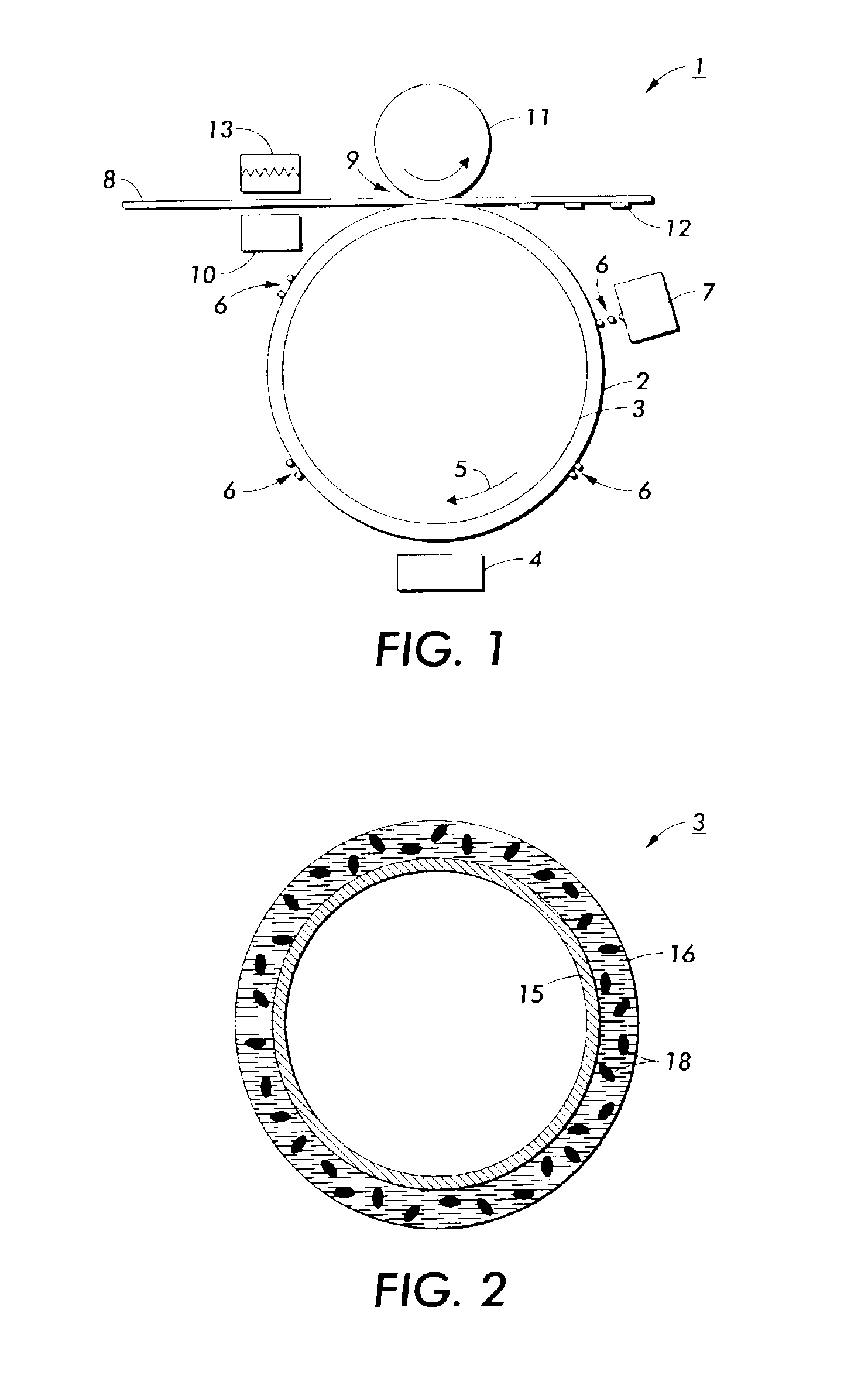
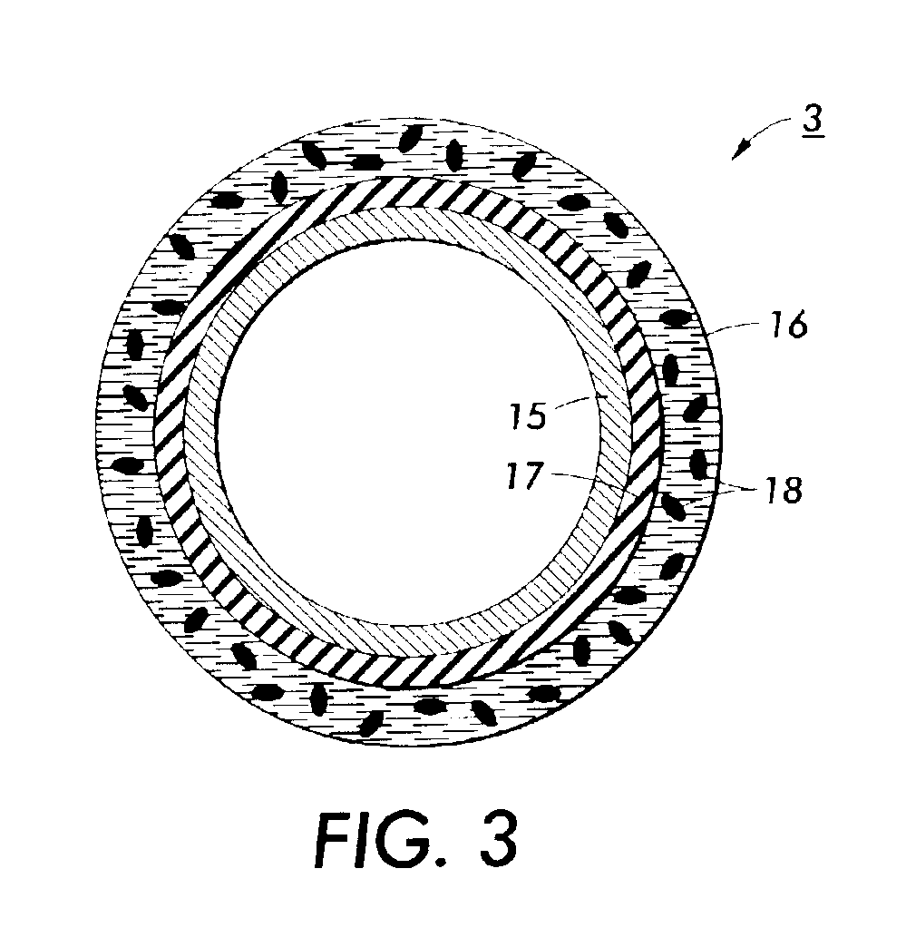
[0081]An aluminum substrate imaging member having the dimensions of about 10 inches long, about 4 inches in diameter, and about 0.25 inches thick, was first sanded with 400 grit sand paper, and cleaned with methyl ethyl ketone. The cleaned drum was then air dried, followed by compressed air treatment to remove residual dust particles. The cleaned drum was then coated uniformly with about 3 grams of a primer solution of Chemlok 5150 primer (an amino silane as identified by the manufacturer) solution (9:1 dilution with methanol), and allowed for hydrolysis. The primed aluminum base drum was then air dried and allowed for further primer hydrolysis for at least 30 minutes. The primed drum was usually coated within 48 hours of primer application.
[0082]A fluoroelastomer outer coating solution was prepared by mixing a fluoroelastomer (such as VITON® GF, VITON® B50, TECHNOFLON® P959, or the like), comprising a curati...
example 3
Testing of the Fluoroelastomer Imaging Drum Coatings
[0089]The coated drums prepared in accordance with Examples 1 and 2 were tested in modified Phaser 860 lab solid ink printers.
[0090]The results are shown in Table 3 below.
[0091]
TABLE 3Number of prints with acceptableImaging Memberimage gloss levelExample 1 (nano-sized filler)160,000 printsComparative Example 2 (submicron 50,000 printsfiller)
[0092]The above results from Table 3 demonstrate that by use of the nano-size fillers, the imaging drum printed acceptable image gloss prints for the life of the machine, or 160,000 prints. Conversely, the imaging drum with the coating having submicron-size particles provided unfavorable results, and only printed 50,000 acceptable image gloss level prints.
[0093]The coating having the nano-size filler provides, in embodiments, control of surface roughness, lower coefficient of friction, less surface damage, durability against paper handling, and improved gloss life.
example 4
Preparation of Sol-Gel Nano-Size Silica Particles in VITON® GF Layer
[0094]An aluminum substrate imaging member having the dimensions of about 10 inches long, about 4 inches in diameter, and about 0.25 inches thick, was first sanded with 400 grit sand paper, and cleaned with methyl ethyl ketone. The cleaned drum was then air dried, followed by treatment with compressed air to remove residual dust particles. The cleaned drum was then coated uniformly with about 3 grams of a primer solution of Chemlok 5150 primer (an amino silane as identified by the manufacturer) solution (9:1 dilution with methanol), and allowed for hydrolysis. The primed aluminum base drum was then air dried and allowed for further primer hydrolysis for at least 30 minutes. The primed drum was usually coated within 48 hours of primer application.
[0095]The polymer nanocomposite composition containing nano-size silica particles was prepared as follows. A stock solution of VITON® GF was prepared by dissolving 250 g of ...
PUM
| Property | Measurement | Unit |
|---|---|---|
| particle size | aaaaa | aaaaa |
| particle size | aaaaa | aaaaa |
| particle size | aaaaa | aaaaa |
Abstract
Description
Claims
Application Information
 - R&D
- Intellectual Property
- Life Sciences
- Materials
- Tech Scout
- Unparalleled Data Quality
- Higher Quality Content
- 60% Fewer Hallucinations
Browse by: Latest US Patents, China's latest patents, Technical Efficacy Thesaurus, Application Domain, Technology Topic, Popular Technical Reports.
© 2025 PatSnap. All rights reserved.Legal|Privacy policy|Modern Slavery Act Transparency Statement|Sitemap|About US| Contact US: help@patsnap.com


