This helps you quickly interpret patents by identifying the three key elements:
Problems solved by technology
Method used
Benefits of technology
Benefits of technology
[0018]It is other object of the invention to present a scroll thrust bearing having both-end conical rollers as rolling elements, much lower in cost and higher in precision as compared with the prior art, large in load capacity, and excellent in durability.
[0019]It is another object of the invention to present a scroll thrust bearing having both-end conical roller bearings of long life, and notably extended in the life of the bearing.
[0023]That is, in the scroll thrust bearing of the invention, in the track pockets of a pair of bearing plates, the both-end conical rollers roll as shown in FIG. 28(b), and relative and smooth scroll swirl of the both bearing plates is assured, while relative rotation of both bearing plates is prevented.
[0027]More specifically, since the shape and dimension of the both-end conical rollers are designed to satisfy the above relation, with respect to the preset scroll swirl radius (R) of the both-end conical roller, the section curvature in the contact portion with the track of the both bearing plates on the conical surface of the both-end conical roller is as small as possible in practical range. Therefore, the surface pressure (pressure per unit area) acting on the conical surface of the both-end conical roller is as small as possible, and a sufficient durability is assured practically.
Problems solved by technology
However, such spheres are supported in point contact, and are inferior in durability, not withstanding for long in the conditions of high speed and heavy load, and there were problems in life and others.
In spite of such excellent durability, however, the scroll type compressor having such thrust force support structure (f) is not realized yet mainly because the assembling and manufacturing technology of the thrust force support structure (f) is not established yet.
In such structure, however, in the assembling process of the scroll structure and assembling process into the scroll structure, only a slight vibration may disturb the configuration of the both-end conical rollers K, K, . . . . It is hence difficult to array all both-end conical rollers K, K, .
. . in a specific direction and assemble into the track, and mass production by automatic assembling is not yet perfect structurally.
Method used
Image
Click on the blue label to locate the original text in one second.
Reading with bidirectional positioning of images and text.
Examples
embodiment 1
[0085
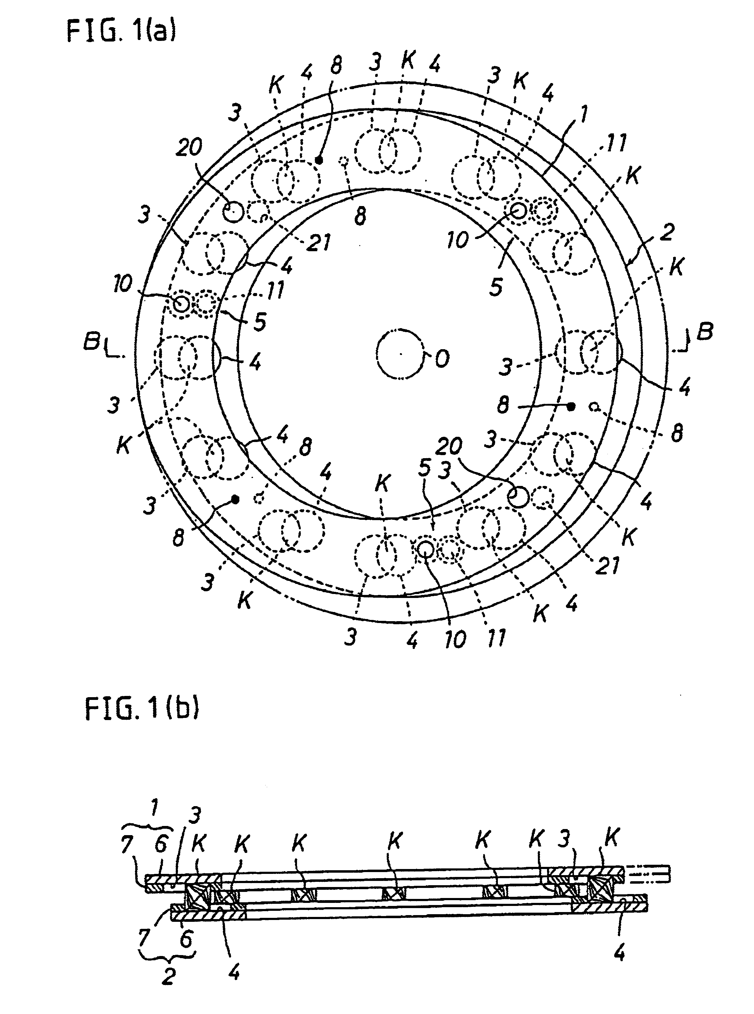
[0086]A roller bearing of the invention is shown in FIG. 1 to FIG. 6. This roller bearing is, specifically, a scroll thrust bearing preferably used as thrust force support structure in a scroll type compressor as shown, for example, in FIG. 28(a).
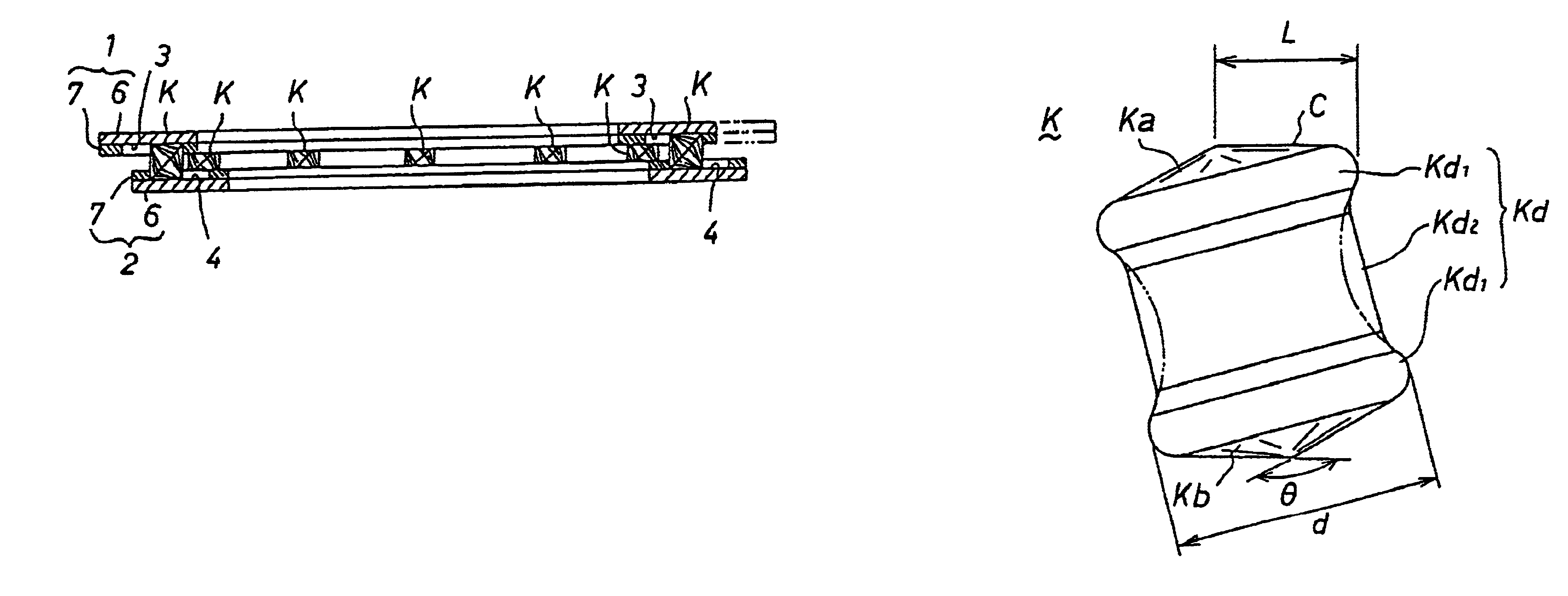
[0087]The scroll thrust bearing comprises a pair of parallel bearing plates 1, 2, and plural (12 in the shown example) track pockets 3, 4 disposed oppositely to them, and a both-end conical roller K is rotatably held each between the pair of confronting track pockets 3, 4. The bearing plates 1, 2 are linked and held so as not to be separated from each other by a linking mechanism 5 as coupling means, so that a scroll thrust bearing of unit structure is formed.
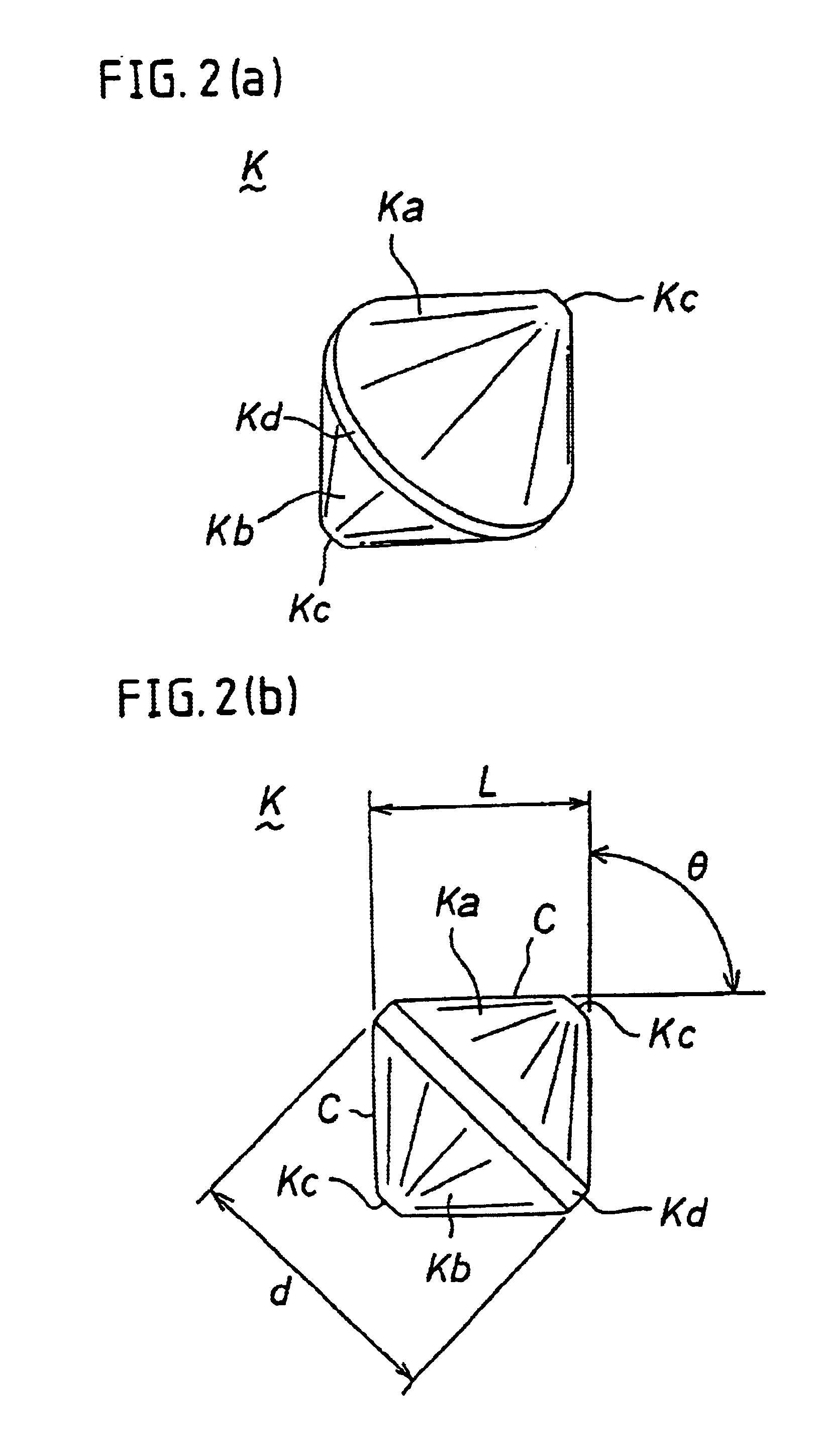
[0088]The both-end conical roller K is disposed between the both bearing plates 1 and 2 so as to be free to roll, and receives the thrust load from the bearing plates 1, 2, and is made of bearing steel.
[0089]The both-end conical roller K is composed, as shown in FIG. 2, of a pair ...
embodiment 2
[0124
[0125]This embodiment is shown in FIG. 7 to FIG. 11. The scroll thrust bearing of the embodiment comprises a plurality of both-end conical rollers K, K, . . . held by a holder 23 rotatably between a pair of parallel bearing plates 1, 2, and a rotation preventive mechanism 24 preventing relative rotation of the both bearing plates 1, 2.
[0126]The upper and lower bearing plates 1, 2 are mutually identical in structure. The bearing plates 1, 2 are specifically composed of flat annular races made of bearing steel, and the mutually confronting inside surfaces 1a, 2a of the bearing plates 1, 2 are flat track surfaces for rolling of the both-end conical rollers K, K, . . . .
[0127]The specific structure of the both-end conical roller K is same as in embodiment 1 (see FIG. 2). The both-end conical roller K is rotatably held by the holder 23 between the both bearing plates 1, 2, and one conical surface Ka rolls on the track 1a of the bearing plate 1, and the other conical surface Kb rolls...
embodiment 3
[0154
[0155]This embodiment is shown in FIG. 12. The scroll thrust bearing of the embodiment is modified in the structure of the roller holding pockets 30 for holding the both-end conical rollers K.
[0156]That is, the roller holding pocket 30 of the embodiment is a pocket hole penetrating from upper to lower side of the holding plate 23 same as in embodiment 2 as shown in FIG. 12, but the inside is a holding space of a spherical surface 130a having a slightly larger diameter than the maximum diameter d of the both-end conical roller K.
[0157]The other structures and actions are same as in embodiment 2.
PUM
Abstract
A scroll thrust bearing having both-end conical rollers are rolling elements, being low in cost, high in precision, large in load capacity, and excellent in durability. A plurality of both-end conical rollers are held rotatably between a pair of bearing plates, and the relation of the scroll swirl radius (R) of both-end conical roller and the dimension (H) between opposite tracks of the both bearing plates is set in a range of 1<H / R<5. As compared with the preset scroll swirl radius (R) of both-end conical roller, the section curvature in the contact portion with the tracks of the both bearing plates of the conical surfaces of the both-end conical roller is kept as small as possible in a practical range, so that the surface pressure acting on the conical surfaces of the both-end conical roller is kept as small as possible.
Description
RELATED APPLICATION[0001]This application is a divisional application of application Ser. No. 09 / 584,769, filed on Jun. 1, 2000 now abandoned.BACKGROUND OF THE INVENTION[0002]1. Field of the Invention[0003]The present invention relates to a scroll thrust bearing, and more particularly to a structure of a scroll thrust bearing having a plurality of both-end conical rollers as rolling elements, and preferably used for thrust force support structure in, for example, a scroll type compressor.[0004]2. Description of the Related Art[0005]The scroll type compressor is a kind of rotary compressors, and it is small in size and free of valve mechanism, and fluid compression is continuous, and as compared with the conventional reciprocating compressors, torque fluctuations and vibrations are small and high speed operation is possible, and hence it is recently applied widely.[0006]This type of compressor has a thrust force support structure for enabling scroll driving. The support structure com...
Claims
Application Information
Patent Timeline
Application Date:The date an application was filed.
Publication Date:The date a patent or application was officially published.
First Publication Date:The earliest publication date of a patent with the same application number.
Issue Date:Publication date of the patent grant document.
PCT Entry Date:The Entry date of PCT National Phase.
Estimated Expiry Date:The statutory expiry date of a patent right according to the Patent Law, and it is the longest term of protection that the patent right can achieve without the termination of the patent right due to other reasons(Term extension factor has been taken into account ).
Invalid Date:Actual expiry date is based on effective date or publication date of legal transaction data of invalid patent.

