Mechanism for extendable rotor blades for power generating wind and ocean current turbines and means for counter-balancing the extendable rotor blade

a technology of wind and ocean current turbines and rotor blades, which is applied in the direction of rotors, marine propulsion, vessel construction, etc., can solve the problems of aircraft fatigue failure, inability to address the requirements of wind or ocean current applications, and inability to address bielawa patents, etc., to achieve the effect of reducing the number of aircra

Inactive Publication Date: 2005-08-02
UNITED TECH CORP
View PDF26 Cites 81 Cited by
  • Summary
  • Abstract
  • Description
  • Claims
  • Application Information

AI Technical Summary

Benefits of technology

[0035]The present invention relates to a fluid flow power generating system in which a turbine is mounted on a structure (such as a tall wind tower or a tethered underwater nacelle) that is held stationary in the horizontal axis with reference to the fluid flow. The turbine includes a rotor having a main blade section connected to a rotor hub and an extender section. An adjustin

Problems solved by technology

Wood does not address the requirements of a wind or ocean current application, wherein the rotors are in alignment with and are driven by a flowing medium and do not move with respect to the flowing medium.
The Bielawa patent does not address problems that arise with respect to an extendable rotor blade system that is fixed with respect to the flowing medium, whether the medium is air or water or any other fluid-flow medium.
These references do not address the requirements of a wind or ocean current applications, wherein the rotor is driven by a flowing medium and does not move with respect to the flowing medium and where durability and fatigue resistance are paramount to the success of such system, and wherein forces acting upon the rotor vary significantly during each revolution.
The mechanisms suggested in the prior art for controlling variable diameter rotors for tilt rotors and aircraft are susceptible to fatigue failures and require extensive maintenance.
Wind turbines and ocean current turbines operate in environmental conditions

Method used


Image

  • Mechanism for extendable rotor blades for power generating wind and ocean current turbines and means for counter-balancing the extendable rotor blade
  • Mechanism for extendable rotor blades for power generating wind and ocean current turbines and means for counter-balancing the extendable rotor blade
  • Mechanism for extendable rotor blades for power generating wind and ocean current turbines and means for counter-balancing the extendable rotor blade

Examples


Embodiment Construction

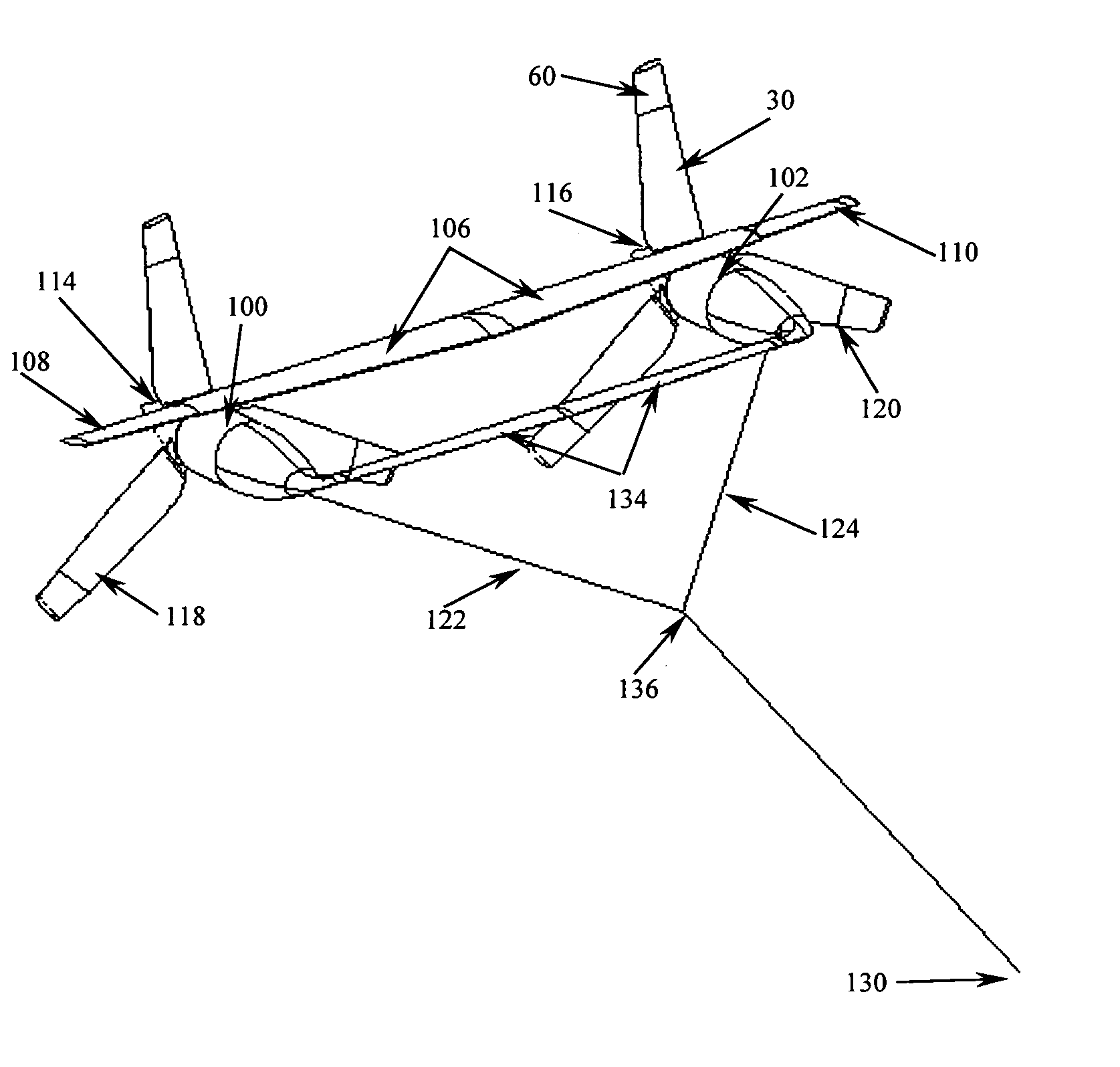
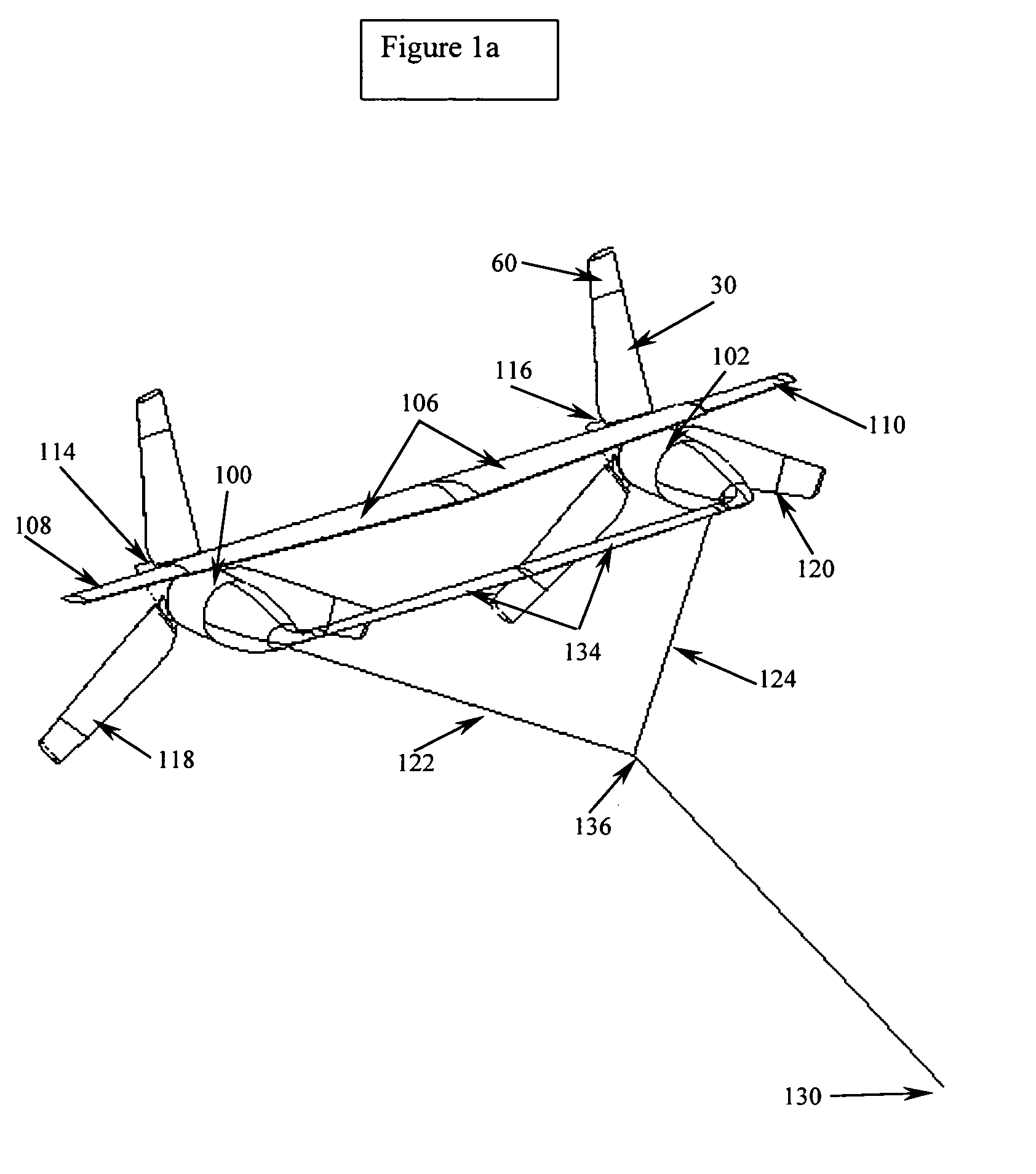
[0045]FIG. 1a illustrates an underwater power-generating device. The underwater power-generating device includes a pair of electric generators housed in fluid-tight nacelles, 100, 102, which are connected together by a hydrofoil structure. The hydrofoil structure consists of a central section 106 and a pair of wings outboard of the nacelles (“wing tips”) 108 and 110. The hydrofoil wing tips are canted upward to provide roll stability.

[0046]The central wing 106 contains one or more cylindrical ballast tanks that span the distance between nacelles. The ballast tanks are used to provide variable buoyancy and forward-aft weight shifting between ballast tanks and to serve as the structural members connecting the nacelles. The hydrofoil structure positions and supports the nacelles, 100, 102, on the upper surface of the wing 106 with each of the nacelles located at the ends of the central hydrofoil structure.

[0047]Each generator has a rotor 114 and 116 with variable pitch blades, 118 and ...


PUM


Abstract

A power generating system wherein a turbine is mounted on top of a tower or tethered underwater. The turbine includes a rotor having a main blade section connected to a rotor hub and an extender section. An adjusting device positions the extender section between a retracted position within the main blade section and to an extended position to expose more or less of the rotor to the fluid flow. The adjusting device includes a first web-engaging wheel anchored at a hub end of the main blade section and a second web-engaging wheel anchored at a distal end of the main blade section. A web is wound around the first and second web-engaging wheels. The extender section is attached to the web at a hub end of the extender section. A generator is connected to the turbine for generating electrical energy.

Description

CROSS-REFERENCE TO RELATED APPLICATIONS[0001]This application is a continuation in part of U.S. Provisional Patent Application No. 60 / 362,139, filed Mar. 7, 2002, and is related to commonly assigned copending application Ser. No. 10 / 039,825, (U.S. Pat. No. 6,726,439 B2) of Amir S. Mikhail and Geoffrey F. Deane filed Oct. 25, 2001 and granted Apr. 27, 2004, entitled “Extendable Rotor Blades For Power Generating Wind And Ocean Current Turbines And Means For Operating Below Set Rotor Torque Limits”, both of which applications are incorporated herein by reference.BACKGROUND OF THE INVENTION[0002]1. Field of the Invention[0003]This invention relates to electric power-generating devices, such as wind turbines and ocean current turbines, and more particularly to an apparatus for extending and retracting extendable rotors of horizontal axis, axial flow wind or water turbines.[0004]2. Description of the Prior Art[0005]U.S. Pat. No. 3,606,571 of Wood entitled “Stowed Rotor” granted Sep. 20, 1...

Claims


Application Information

Patent Timeline
IPC IPC(8): F01D7/00F03B17/06F03D1/00
CPCF03B17/061F03D1/00F05B2240/97Y02E10/28Y02E10/72Y02E10/30Y02E10/20
Inventor DEHLSEN, JAMES G. P.
Owner UNITED TECH CORP
Why Eureka
Try Eureka