Apparatus and method for anchoring sutures

a technology of sutures and apparatus, applied in the field of suture anchors, can solve the problems of putting undue stress on the suture, affecting the stability of the suture, and the type of suture anchor can be costly and difficult to manufacture, so as to reduce the risk of fracture, and reduce the effect of later complications

Inactive Publication Date: 2005-08-02
DEPUY SYNTHES PROD INC
View PDF68 Cites 233 Cited by
  • Summary
  • Abstract
  • Description
  • Claims
  • Application Information

AI Technical Summary

Benefits of technology

[0011]It is an object of this invention to provide a suture anchor which is simple and inexpensive to manufacture and easy to insert, as well as a method of inserting and deploying the suture anchor which i

Problems solved by technology

Because two different materials are used, this type of suture anchor can be costly and difficult to manufacture.
Moreover, the joining of two dissimilar metals leads to potential flaws and potential breakage at the joint or weld point.
One disadvantage associated with this type of anchor is that tugging on the suture to reorient the anchor may put undue stress on the suture (particularly at the base of the slot in Hayhurst).
Furthermore, the introduction technique is unduly complicated, requiring several types of insertion tools.
It is believed that inserting and seating the Noblitt suture anchor may present additional technical difficulties because of the portion of the suture anchor which is offset from the central portion of the elongated body.
A di

Method used


Image

  • Apparatus and method for anchoring sutures
  • Apparatus and method for anchoring sutures
  • Apparatus and method for anchoring sutures

Examples


example 1

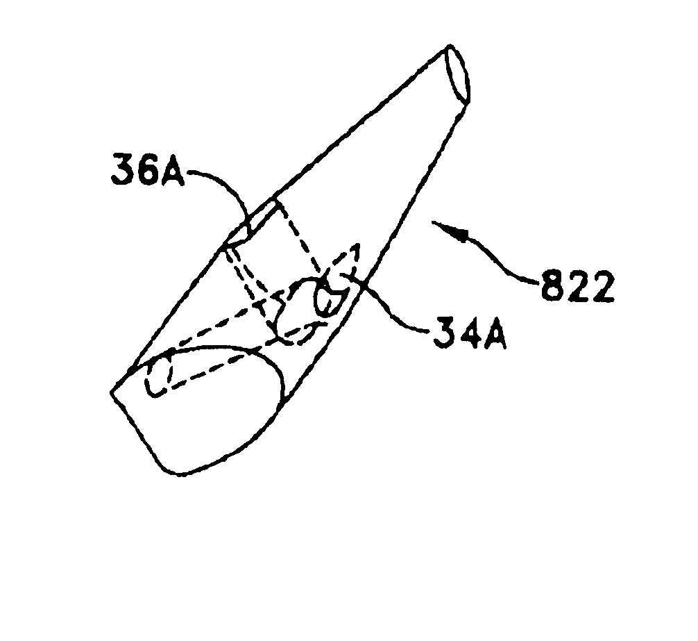
[0083]Suture anchors substantially as shown in FIGS. 5 and 6, made from bony allograft, were fashioned from 4-8 mm strips of hydrated cortical bone. Initial conical shaping was done on a medium grain stone grinding wheel. The conical shape was then made uniform with a mill made from a pencil sharpener. An anchor bore and an accessory bore were then drilled using a guide jig to control size and location. Final smoothing and shaping including the cylindrical portion of the anchor was done with a dremel tool. The dimensions of the final suture anchor were as set out above for the preferred embodiment of suture anchor 522.

[0084]An insertion tool substantially as shown in FIG. 12 was shaped from 0.062 in. (1.575 mm) NITINOL.™. ground to a tapered tip (using two grinding wheels on a centerless grinding tool). A handle was fashioned from a stainless steel dowel drilled to accept the body of the insertion tool.

[0085]Human cadaveric humerus and pig pelvis in which a hole of about 3 mm was dr...

example 2

[0089]Suture anchors substantially as shown in FIGS. 5 and 6, made of the biocompatible polymer polysulfone, were fashioned by drilling cylindrical stock polysulfone. The suture anchors were then shaped on a lathe. The bores were then radiused and the ends cut. The dimensions were as set out above for the preferred embodiment of suture anchor 522.

[0090]An insertion tool fashioned as described in Example 1 was used to implant the anchors into specimens of human humerus and pig pelvis. Several tests of suture anchor strength were performed as outlined in Example 1.

[0091]The measured failure strengths of a suture anchor formed from polysulfone was consistently measured at greater than 32 pounds. This measured failure strength far exceeds industry standards.


PUM


Abstract

A suture anchor having a conical surface and a bore in which an end of an insertion tool is inserted. The insertion end of the insertion tool is made of material having elastic properties. The bore and base of the suture anchor are angled with respect to the central axis of the suture anchor and preferably are parallel to each other. During insertion, the suture anchor is reoriented to fit into the hole, thereby bending the elastic end of the insertion tool. When the suture anchor is within cancellous bone tissue, the elastic properties of the insertion tool deploys the suture anchor to an orientation in which the suture anchor cannot fit through the bone hole, thereby firmly anchoring the suture anchor in the human bone.

Description

[0001]This is a continuation of U.S. patent application Ser. No. 09 / 265,022, filed Mar. 9, 1999 now U.S. Pat. No. 6,146,408, by Edwin C. Bartlett for APPARATUS AND METHOD FOR ANCHORING SUTURES, which is a continuation of U.S. patent application Ser. No. 08 / 851,583, filed May 5, 1997 now U.S. Pat. No. 5,879,372, by Edwin C. Bartlett for APPARATUS AND METHOD FOR ANCHORING SUTURES, which is a continuation of U.S. patent application Ser. No. 08 / 308,286, filed Sep. 19, 1994 now U.S. Pat. No. 5,626,612 by Edwin C. Bartlett for APPARATUS AND METHOD FOR ANCHORING SUTURES, which is a continuation-in-part of 08 / 124,163 filed Sep. 20, 1993, now U S. Pat. No. 5,540,718; issued Jul. 30, 1996 to Edwin C. Bartlett.BACKGROUND OF THE INVENTION[0002]This invention relates to an apparatus and method for anchoring sutures to a live human bone. More particularly, this invention relates to a suture anchor made of a substantially rigid, preferably biocompatible material, and most preferably a material tha...

Claims


Application Information

Patent Timeline
IPC IPC(8): A61B17/04A61F2/28A61B17/00A61B17/56A61B17/58
CPCA61B17/0401A61B2017/00862A61B2017/0409A61B2017/0414A61B2017/0416A61B2017/0458A61F2/0811A61F2002/2835
Inventor BARTLETT, EDWIN C.WENSTROM, JR., RICHARD F.
Owner DEPUY SYNTHES PROD INC
Why Eureka
Try Eureka