Piezoelectric transducer, manufacturing method of piezoelectric transducer and pulse wave detector

Inactive Publication Date: 2005-08-02
SEIKO INSTR INC
View PDF10 Cites 5 Cited by
  • Summary
  • Abstract
  • Description
  • Claims
  • Application Information

AI Technical Summary

Benefits of technology

[0016]According to such a constitution, it becomes possible to provide an acoustic matching layer with the optimum thickness, which is capable of being easily manufactured. As a result, it becomes possible to provide a piezoelectric transducer with a low cost and a high sensitivity.

Problems solved by technology

With respect to the conventional piezoelectric transducer to be used as the ultrasonic probe, it is necessary to apply a special patterning to the piezoelectric element, which involves a problem such that the conventional piezoelectric transducer is difficult to manufacture the manufacturing cost of the conventional constitution is higher.
If it becomes thicker, the ultrasonic wave is attenuated and as a result, detection sensitivity of the pulse wave or the like is deteriorated.
Therefore, in the case of bonding the conducting wire to the piezoelectric element with the conductive adhesive or the like such as the piezoelectric transducer embedded in the resin, it is necessary to make the thickness of the conductive adhesive and the thickness of the conductive wire less than or equal to that of the above mentioned acoustic matching layer, so that it is very difficult to manufacture such a piezoelectric transducer and the thickness of the acoustic matching layer becomes thicker than the optimum thickness.
This involves a problem such that the detection sensitivity has been deteriorated.
Additionally, if the conductive wire made of a thick or hard material is used, a vibration property of the piezoelectric element comes under the influence and if the thick conductive wire is used, unnecessary stress and an unnecessary fixed point are generated in the piezoelectric element and a vibration mode comes under the influence.
Further, a resonant frequency is deviated and impedance of the resonant frequency is changed, so that it is not possible to effectively vibrate the piezoelectric element.
As a result, this involves a problem such that a desired detection sensitivity cannot be obtained.

Method used


Image

  • Piezoelectric transducer, manufacturing method of piezoelectric transducer and pulse wave detector
  • Piezoelectric transducer, manufacturing method of piezoelectric transducer and pulse wave detector
  • Piezoelectric transducer, manufacturing method of piezoelectric transducer and pulse wave detector

Examples


first embodiment

[First Embodiment]

[0043]With reference to FIGS. 1 to 10, a first embodiment of a pulse wave detector by the use of a piezoelectric transducer according to the present invention will be explained in detail below.

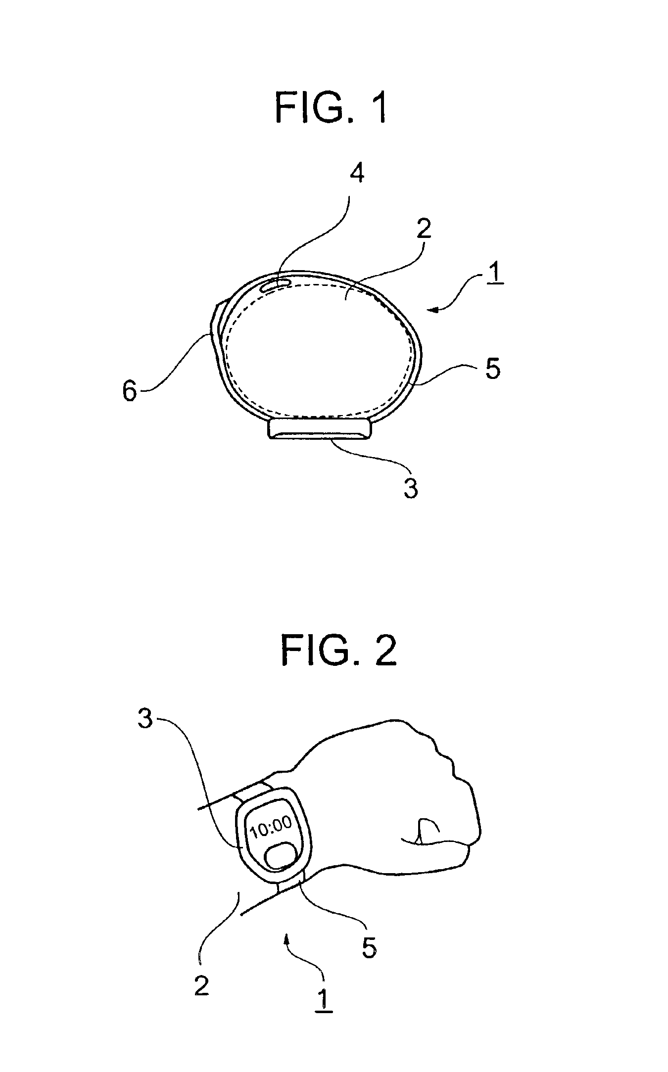
[0044]In the beginning, with reference to FIG. 1 and FIG. 2, an outer shape of a pulse wave detector 1 will be described. FIG. 1 is a side view for showing a constitution of the outer shape of the pulse wave detector 1, to which the present invention is applied and FIG. 2 shows a condition that the pulse wave detector 1 shown in FIG. 1 is mounted on a living body 2 (i.e., an arm).

[0045]As shown in FIG. 1, the pulse wave detector 1 schematically consists of a processing unit 3, a piezoelectric transducer 4, a band 5 and a fastening plate 6. As shown in FIG. 2, it is possible to wear the pulse wave detector 1 at all times by fitting it to the living body 2. In this case, the processing unit 3 and the piezoelectric transducer 4 are attached to the band 5 to be fit to the living ...

second embodiment

[Second Embodiment]

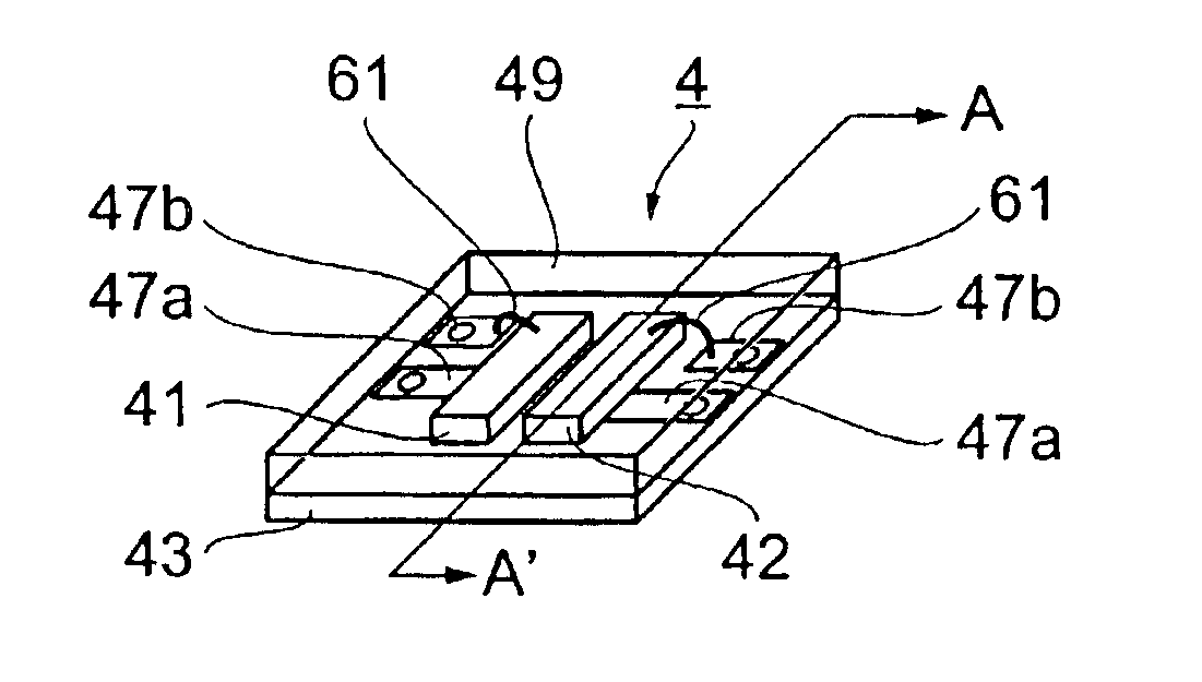
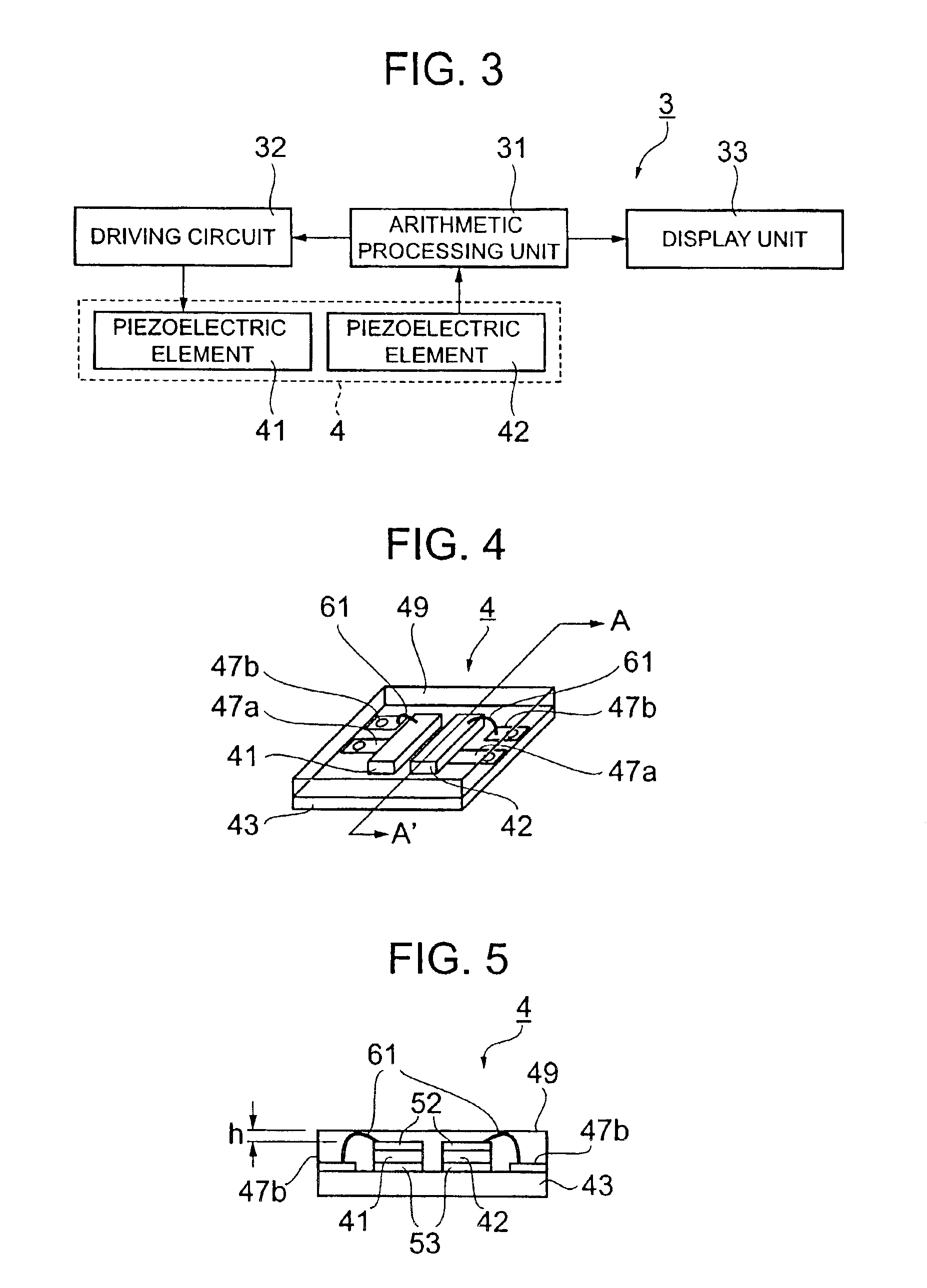
[0074]With reference to FIGS. 11 to 12, the piezoelectric transducer according to the present invention will be explained below. FIG. 11 is a cross sectional view of the piezoelectric transducer 4 (i.e., an A-A′ cross sectional view such that the piezoelectric transducer 4 is cut in a longitudinal direction of the PZT in FIG. 4). In FIG. 11, a piezoelectric element supporting part 59 is provided on the substrate 43. Here, an electrode 47b is represented by a broken line.

[0075]Vibrating the piezoelectric element 41, the reflection of the ultrasonic wave arises at a boundary surface between the piezoelectric element and other object. This reflected wave causes a noise and it extremely decreases an S / N ratio of the detect signal. In the case that the piezoelectric elements 41 and 42 are directly fixed on the electrode 47b, the electrode to be normally used is made of a copper and a gold, so that the electrode is harder than a layer of the adhesive or the like and the...

third embodiment

[Third Embodiment]

[0081]With reference to FIG. 14, the piezoelectric transducer according to the present invention will be explained below. FIG. 14 is a cross sectional view of the piezoelectric transducer 4 (i.e., a cross sectional view cut in a longitudinal direction of the PZT in FIG. 4).

[0082]As described above, the acoustic matching layer 49 is needed to be set not more than ¼ of the wave length of the ultrasonic wave (in the case of 9.6 MHz, not more than 50 μ). However, in the case that the wire bonding 61 is higher than the acoustic matching layer 49 and in the case that the thickness of the acoustic matching layer 49 should be set lower than the diameter of the wire, as shown in FIG. 14, by making the acoustic matching layer 49 thicker only in the vicinity of the wire bonding 61, the deterioration of the sensitivity is suppressed to the minimum and the wire bonding is capable of being sealed. Further, it is possible to improve durability thereof.

[0083]It is possible to manu...


PUM


Abstract

A piezoelectric transducer comprises: a substrate having first and second substrate electrodes forming input and output terminals, and one or more piezoelectric elements for transmitting a supersonic wave to an object to be measured and receiving a reflected wave from the object. The piezoelectric elements are arranged on the substrate and have a first surface electrode connected to the first substrate electrode and a second surface electrode connected to the second substrate electrode via a conductive member. An acoustic matching layer is superposed on the piezoelectric elements for efficiently propagating the supersonic wave on the second surface electrode. The conductive member has a thickness not more than that of the acoustic matching layer and is embedded in the acoustic matching layer.

Description

BACKGROUND OF THE INVENTION[0001]1. Field of the Invention:[0002]The present invention relates to a piezoelectric transducer and specifically, the present invention relates to a piezoelectric transducer, a manufacturing method of the piezoelectric transducer and a pulse wave detector for detecting the information of the interior of a human body and the interior of an object.[0003]2. Description of the Prior Art:[0004]A conventional piezoelectric transducer to be used as an ultrasonic probe or the like will be explained with reference to FIGS. 16, 17 and 18.[0005]FIG. 16 is a perspective view of a conventional piezoelectric transducer and FIG. 17 is a side view of the piezoelectric transducer shown in FIG. 16.[0006]A piezoelectric transducer 100 consists of an acoustic matching layer 110, a backing material 130, a piezoelectric element 101 and a flexible substrate 120 for applying a voltage to the piezoelectric element.[0007]The piezoelectric transducer 100 is configured in such a ma...

Claims


Application Information

Patent Timeline
IPC IPC(8): B06B1/06A61B5/0245A61B8/00G01N29/24A61B8/02H01L41/09H01L41/187H01L41/22H01L41/29H04R17/00H04R31/00
CPCB06B1/06A61B5/02444G01N2291/044
Inventor MURAMATSU, HIROYUKISHINOGI, MASATAKANAKAMURA, TAKASHI
Owner SEIKO INSTR INC
Why Eureka
Try Eureka