
Limiting ring current in short circuit between adjacent partial wingings by increasing leakage impedance

a short circuit and impedance technology, applied in the direction of variable inductance, automatic controller, electric variable regulation, etc., can solve the problem that the voltage fluctuation caused by a change in node cannot be adjusted between the network node and the end consumer, and the short circuit between adjacent partial wingings cannot be regulated under load, so as to achieve better and more efficient use

Inactive Publication Date: 2005-08-02
HAUER HANJORG
View PDF25 Cites 7 Cited by
  • Summary
  • Abstract
  • Description
  • Claims
  • Application Information

AI Technical Summary

Benefits of technology

[0013]It is a further aim of the invention to provide a device for carrying out this method, which has a simple and robust structure and which can be manufactured economically.
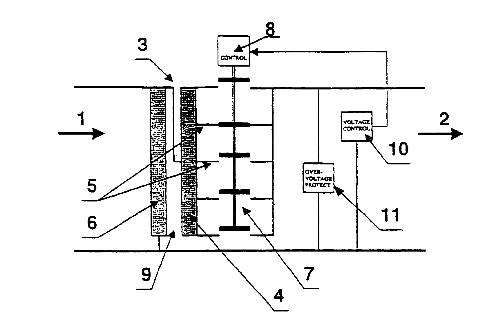
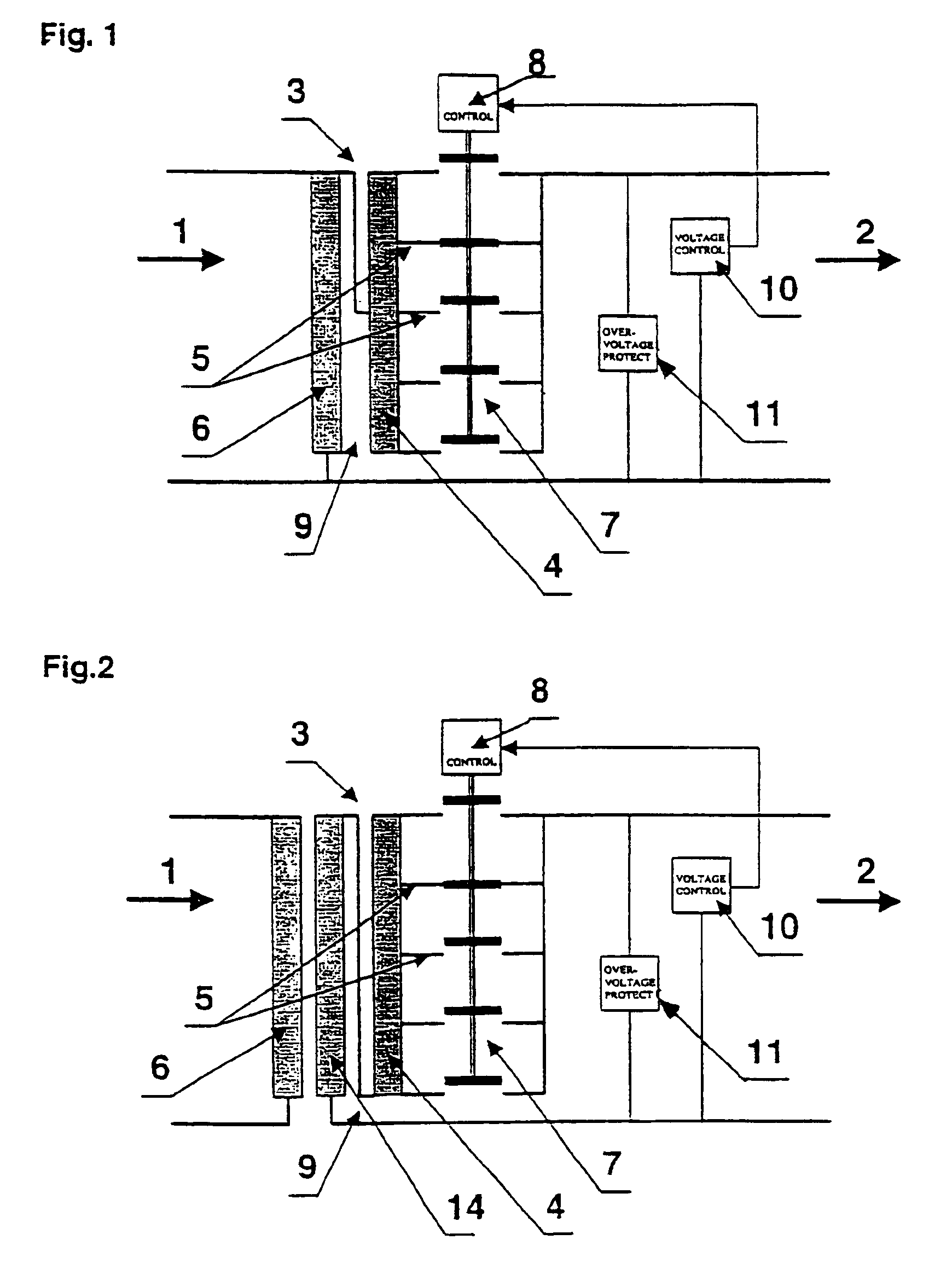
[0016]If the short-circuit impedance of the regulator winding is increased, e.g. by widening the leakage gap, so that the ring circuit in the case of a short circuit between adjacent tappings is of the order of magnitude of the nominal current, the additional transition impedances are not required and the step switch is simplified into a normal transfer switch.
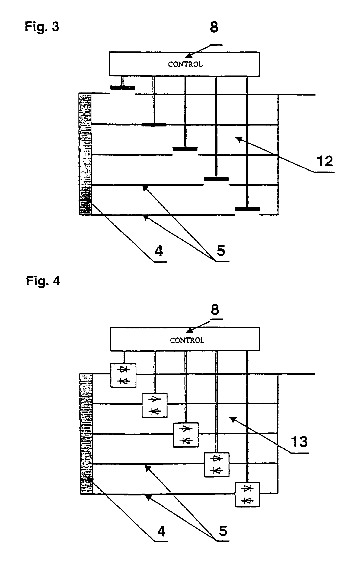
[0019]In a further embodiment of the invention, the transfer switch is a load switch without resistance contact and with only main contacts. As already shown above, such a load transfer switch offers an economical solution.
[0020]In a further embodiment of the invention, the transfer switch is a load selector without resistance contacts. This embodiment of the transfer switch also has an extremely simple structure and can be produced economically.
[0021]In further embodiments of the invention, the transfer switch can also be designed on the basis of a multi-phase camshaft controller or a chain of relays or contactors or a chain of electronic switches, in particular semiconductor switches. These embodiments of the transfer switch also have a simple structure and are extremely reliable in robust operations.

Problems solved by technology

Further transformation to low-voltage level normally cannot be regulated under load.
This network structure is oriented towards the central power supply and has the disadvantage that voltage fluctuations caused by a change in node cannot be adjusted for between the network node and the end consumer.
Thus, the exploitable transfer capacity of the network components downstream from the network nodes is limited by the drop in voltage rather than by thermal strength.
The second requirement results from the fact that during each switching process between two neighbouring tappings they are necessarily briefly connected to each other due to the first requirement, so that there is a ring current equivalent to the transformer short-circuit current between the switch and the relevant winding, the action of which the transformer is unable to withstand, especially during periodical operation.
The disadvantage of the measures used so far to limit the ring current is that they result in complex transition principles and require complex designs of the regulating transformers.

Method used


Image

  • Limiting ring current in short circuit between adjacent partial wingings by increasing leakage impedance
  • Limiting ring current in short circuit between adjacent partial wingings by increasing leakage impedance
  • Limiting ring current in short circuit between adjacent partial wingings by increasing leakage impedance

Examples


Embodiment Construction

[0042]By way of introduction, it is noted that in the described embodiment the same parts and the same states are allocated the same reference numbers and the same component names, whereby the disclosures contained throughout the description can be applied by analogy to the same parts and the same states with the same reference numbers or same component names. Moreover, individual features from the embodiment illustrated can represent independent solutions according to the invention in themselves.

[0043]FIG. 1 shows a device for regulating the electric voltage between one network node 1—represented by the arrow—and one end consumer 2—also represented by an arrow—whereby a regulating transformer 3 in the form of a one-coil transformer is provided for regulating the voltage. This one-coil transformer has a regulating winding with partial windings 4. The regulating winding is connected to the primary winding 6 of the one-coil transformer via a tapping 5, for example via a middle tapping...


PUM


Abstract

Apparatus for regulating an electric voltage in at least one of electric supply networks and consumer units. The apparatus includes a regulating transformer arranged between a network node and at least one end consumer. The regulating transformer utilizes a primary winding and a regulating winding which includes switchable partial windings and a high leakage impedance. The transformer conducts a nominal current. A transfer switch switches the partial windings of the regulating transformer. Adjacent tappings of the partial windings are adapted to short circuit such that, in an event of the short circuit, the high leakage impedance limits a ring current which results from the short circuit to an order of magnitude of the nominal current. The regulating transformer produces both an increase in voltage and a decrease in voltage at the end consumer. This abstract is not intended to define the invention disclosed in the specification, nor intended to limit the scope of the invention in any way.

Description

CROSS-REFERENCE TO RELATED APPLICATIONS[0001]The present application is a continuation of U.S. application Ser. No. 10 / 111,808 filed Apr. 29, 2002, now U.S. Pat. No. 6,762,594 the disclosure of which is expressly incorporated by reference herein in its entirety, which application is a U.S. National Stage of International Application No. PCT / AT00 / 00284 filed Oct. 31, 2000 and claims priority under 35 U.S.C. § 119 of Austrian Patent Application No. A 1838 / 99 filed Nov. 2, 1999.BACKGROUND OF THE INVENTION[0002]1. Field of the Invention[0003]The invention relates to a method for regulating the electrical voltage in electrical supply networks and / or consumer units and a device for carrying out said method.[0004]2. Discussion of Background Information[0005]It is generally known to carry out voltage regulation only in the central network nodes of high or medium voltage networks. Further transformation to low-voltage level normally cannot be regulated under load. This network structure is o...

Claims


Application Information

Patent Timeline
Patent Type & Authority Patents(United States)
IPC IPC(8): G05F1/20G05F1/10H02H7/04H02H7/055
CPCG05F1/20H02H7/055
Inventor HAUER, HANJORG
Owner HAUER HANJORG
Learn More