Dot-clock adjustment method and apparatus for a display device, determining correctness of dot-clock frequency from variations in an image characteristic with respect to dot-clock phase

Inactive Publication Date: 2005-08-02
MITSUBISHI ELECTRIC CORP
View PDF15 Cites 36 Cited by
  • Summary
  • Abstract
  • Description
  • Claims
  • Application Information

AI Technical Summary

Benefits of technology

[0011]An object of the present invention is to provide a dot-cloc

Problems solved by technology

A problem with this method is that it assumes that the image is always intended to fill the entire width of the display screen.
The adjustment fails when this assumption is false, as when an image with a black border is displayed.
One problem with this method is illustrated in FIG. 5, which shows the same image displayed at the same incorrect dot-clo

Method used


Image

  • Dot-clock adjustment method and apparatus for a display device, determining correctness of dot-clock frequency from variations in an image characteristic with respect to dot-clock phase
  • Dot-clock adjustment method and apparatus for a display device, determining correctness of dot-clock frequency from variations in an image characteristic with respect to dot-clock phase
  • Dot-clock adjustment method and apparatus for a display device, determining correctness of dot-clock frequency from variations in an image characteristic with respect to dot-clock phase

Examples


first embodiment

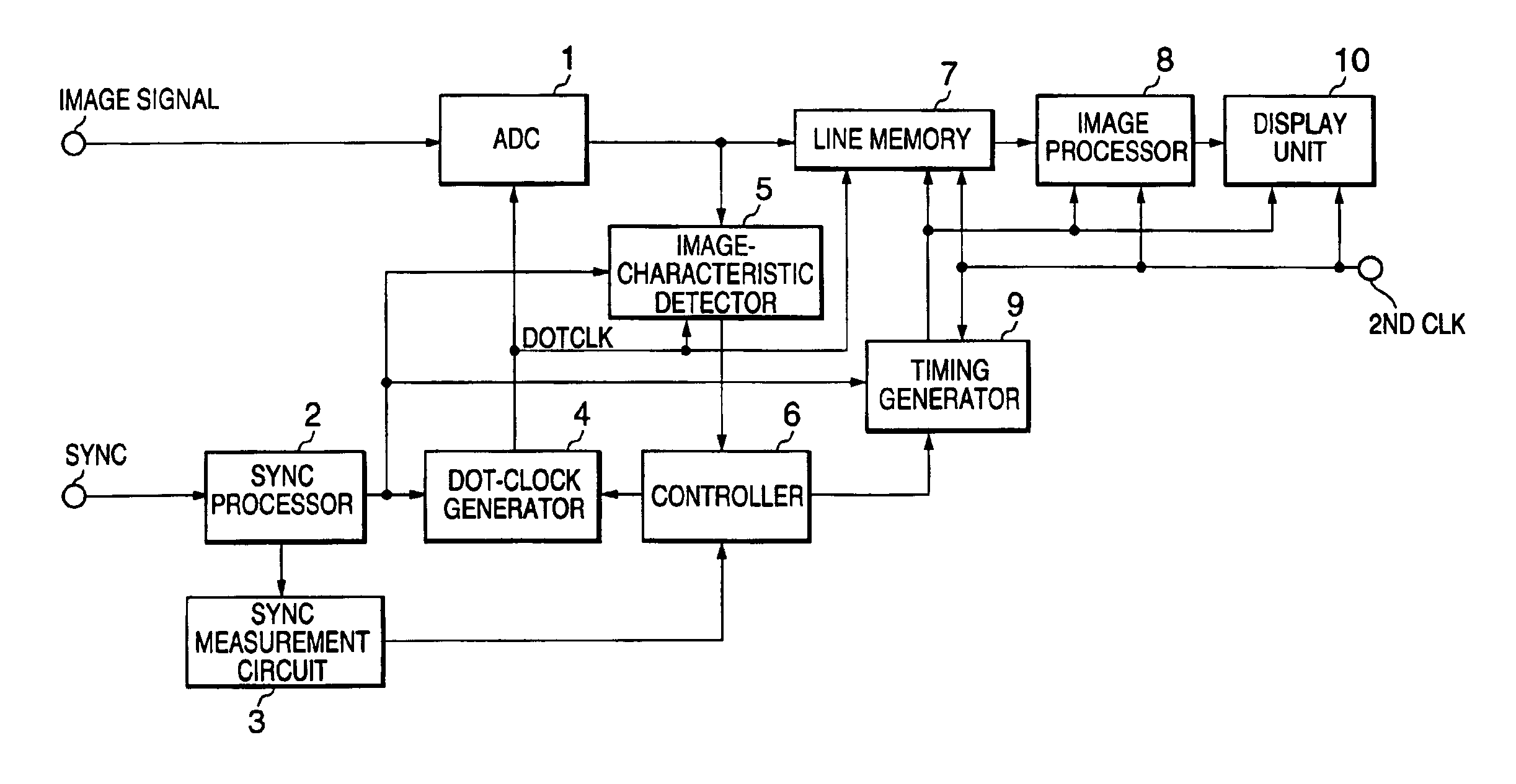
[0044]Referring to FIG. 6, the first embodiment is a display apparatus comprising: an analog-to-digital converter (ADC) 1 that samples an input image signal in synchronization with a dot clock (DOTCLK), thereby converting the image signal to digital data; a synchronizing signal (SYNC) processor 2 that processes an input composite synchronizing signal to obtain a horizontal synchronizing signal and a vertical synchronizing signal; a synchronizing signal measurement circuit 3 that measures various properties of the horizontal and vertical synchronizing signals; a dot-clock generator 4 that generates the dot clock from the horizontal synchronizing signal; an image-characteristic detector 5 that calculates image characteristics from the image data output by the ADC 1; a controller 6 that controls the dotclock generator 4, adjusts the frequency and phase of the dot clock according to the information obtained by the synchronizing signal measurement circuit 3 and image-characteristic detec...

second embodiment

[0074]A further advantage of the second embodiment is that the characteristic curve obtained from a single pair of pixels is unlikely to be affected by clock jitter or noise.

[0075]Next, a third embodiment will be described. The third embodiment uses the maximum absolute difference characteristic to select the address used in the second embodiment.

[0076]Referring to FIG. 14, the image-characteristic detector 5 in the third embodiment comprises an absolute-difference calculator 11, an absolute-difference buffer 14, a maximum-value detector 15, and an address register 16. The maximum-value detector 15 detects the maximum absolute difference output from the absolute-difference calculator 11, as in the preceding embodiments, and also detects the address of a pair of pixels yielding this maximum absolute difference. The address register 16 stores the address detected by the maximum-value detector 15, and supplies this address to the absolute-difference buffer 14. The absolute-difference c...

third embodiment

[0081]For example, if the displayed image is a natural image with a black border, the third embodiment may select a comparatively bright pixel at an edge of the natural image and an adjacent pixel in the black border, thereby obtaining a greater absolute difference than could be obtained by selecting two pixels within the natural image itself. As a result, the characteristic curve obtained in the phase-adjustment procedure will have clearly defined maxima and minima, enabling the phase to be adjusted accurately.

[0082]In a variation of the third embodiment, instead of using the address that happens to be left in the address register 16 at the end of the frequency-adjustment procedure, the controller 6 provisionally selects a phase that maximized the maximum absolute difference characteristic, as in the first embodiment, and sets the dot clock to this phase. The image-characteristic detector 5 then measures the maximum absolute difference characteristic again, to load the address regi...


PUM


Abstract

The frequency of the dot clock in an image display device is adjusted by calculating a first image characteristic from the differences between adjacent picture elements, varying the phase of the dot clock, determining whether the frequency of the dot clock is correct from the way the first image characteristic varies according to the phase of the dot clock, and changing the frequency if it is incorrect. The first image characteristic is, for example, the maximum difference, the histogram distribution of the differences, or a ratio calculated from the histogram. The phase of the dot clock may be adjusted according to a second image characteristic, such as the difference between a single pair of pixel values, which is also measured over a range of dot-clock phase settings.

Description

BACKGROUND OF THE INVENTION[0001]The present invention relates to the adjustment of the dot clock in a matrix display device such as a liquid-crystal panel, digital micromirror device (DMD), plasma display panel (PDP), or field-emission display (FED).[0002]These devices commonly use an analog-to-digital converter (ADC) to convert an analog image signal to the digital the signal needed for a matrix display. The dot clock is the sampling clock of the ADC. Before the display of the image begins, the dot clock must be adjusted in frequency and phase so that the analog image signal will be sampled at the correct points. Various methods of performing these adjustments automatically are known.[0003]For example, Japanese Unexamined Patent Application No. 11-175033 discloses the liquid crystal display device shown in FIG. 1, having an ADC 101, a phase-locked loop (PLL) 102, a clock phase automatic adjusting means 103, a counter 104, an image detector 105, a pulse generator 106, and a control...

Claims


Application Information

Patent Timeline
IPC IPC(8): G09G5/18G09G5/00H04N5/66G09G5/36
CPCG09G5/008G09G5/18
Inventor SOMEYA, JUNOKUNO, YOSHIAKI
Owner MITSUBISHI ELECTRIC CORP
Why Eureka
Try Eureka