Triangulated bicycle pedal support structure

a pedal support and triangular technology, applied in the field of triangular bicycle pedal support structures, can solve the problems of multiple structural segments and inherent structural efficiency, and achieve the effect of reducing high bending stress

Inactive Publication Date: 2005-08-09
ODOM PAUL
View PDF25 Cites 1 Cited by
  • Summary
  • Abstract
  • Description
  • Claims
  • Application Information

AI Technical Summary

Benefits of technology

[0007]This invention replaces the double ended crank arm design currently used on bicycles, with a triangulated crank structure. Triangulation is accomplished by replacing a straight bar type structure that connects the spindle to the pedal shaft end of a crank arm, with a split structure that has two separate tube segments, spaced away from a line between the spindle end and the corresponding pedal shaft attachment loc

Problems solved by technology

The inherent structural efficiency problem in a triangulated

Method used


Image

  • Triangulated bicycle pedal support structure
  • Triangulated bicycle pedal support structure
  • Triangulated bicycle pedal support structure

Examples


Embodiment Construction

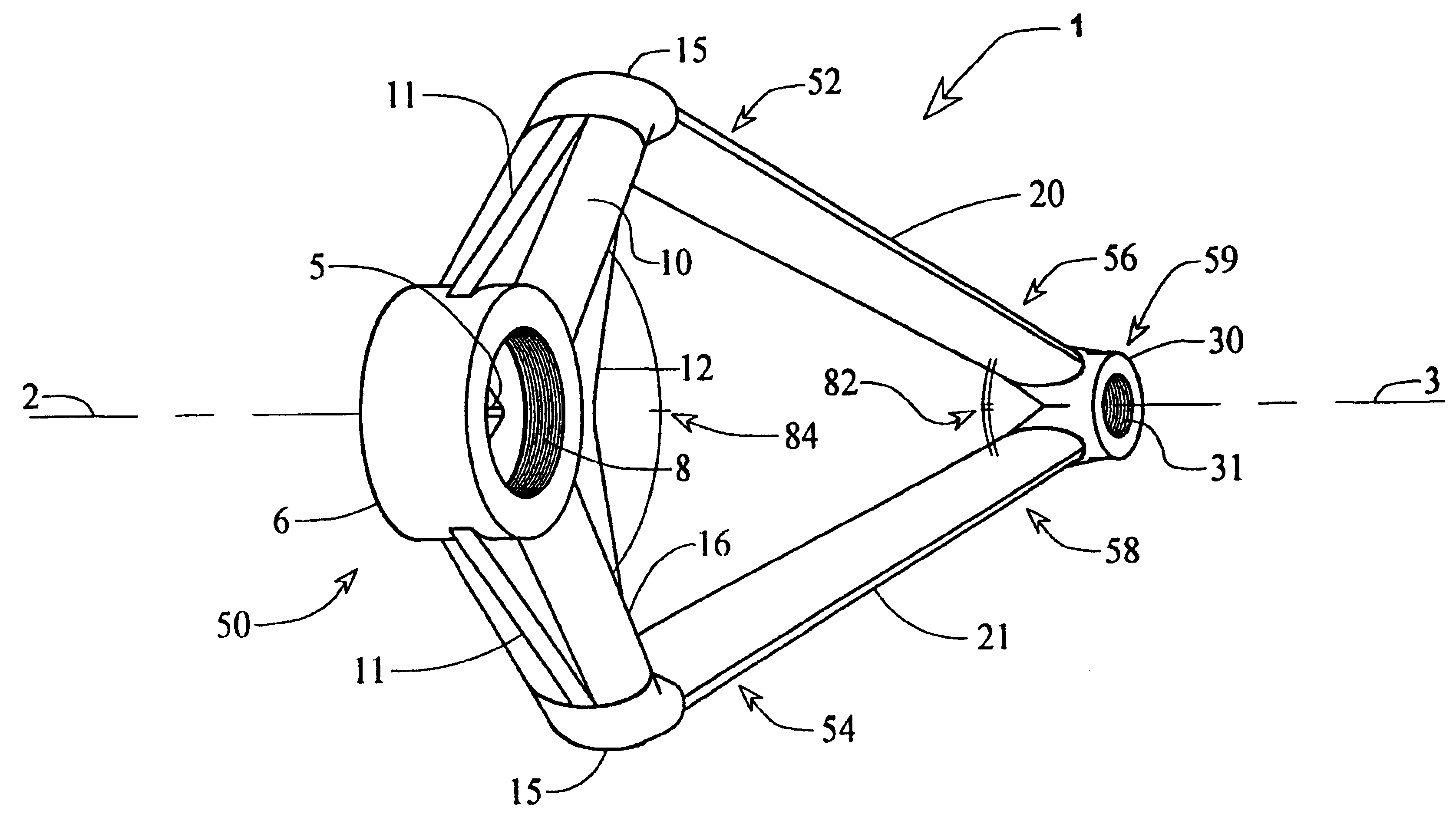
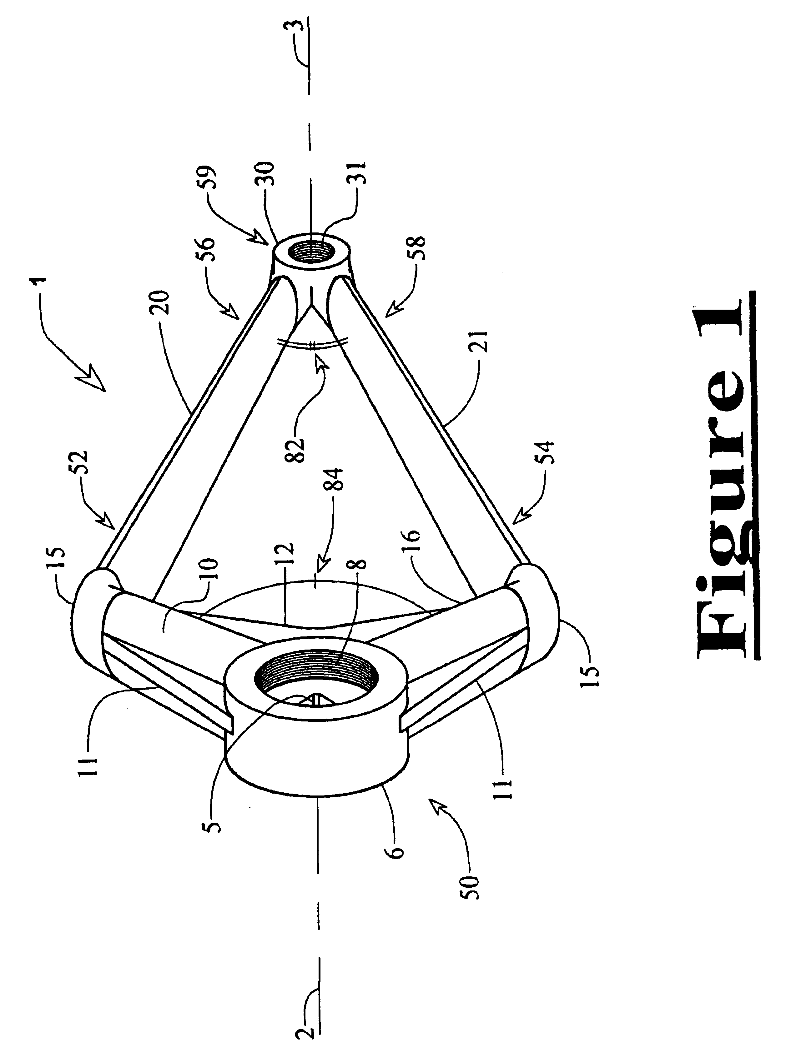
[0018]FIG. 1 discloses a structure 1 for rotatively connecting the pedal of a bicycle to the spindle of a bicycle. Structure 1 comprises a hub 6 which includes an opening 5 to receive the end of a spindle, which rotates on an axis 2. Hub 6 further includes internal threading 8 recessed from its outer face for the purpose of securing a threaded cap which can cover the outer opening of the hub. According to one preferred embodiment of this invention structure 1 comprises two struts, preferably a first connection strut 10 and a second connection strut 16, attached to hub 6, which extend radially away from the center of hub 6, preferably at an attachment angle 84 of less than 200° and optimally less than 180°. While these struts 10, 16 are generally round and hollow in the preferred embodiment, they may be of any cross sectional profile, including rectangular, round, elliptical, “C” or “D” or “I beam” shaped, etc. First connection strut 10 and second connection strut 16 may or may not t...


PUM


Abstract

A bicycle with a triangulated crank structure replaces the single span crank arm which connects the spindle to the foot pedal on bicycles today. The triangulated crank structure is typically comprised of several sections including two linear spans of structural material arranged so that one end of each linear span connects with the other to form the vertex of an acute angle, proximate to a pedal attachment area. From the vertex, the linear spans diverge and each connects at its opposite end to separate locations on a structural element attached to an end of the bicycle's crankshaft or spindle.

Description

BACKGROUND OF THE INVENTION[0001]1. Field of the Invention[0002]The invention relates primarily to bicycles, but also to any other human powered vehicles, watercraft, or exercise devices which utilize a foot pedal or handgrip for the operator to convert rotational motion and / or linear motion of his feet or hands, into work, in order to activate the device.[0003]2. Description of Prior Art[0004]Bicycle crank arms in general, provide a means for physically connecting the foot pedals of the bicycle to the crankshaft of the bicycle. In some cases, one of the crank arms is also attached to a chain sprocket, or a set of axially concentric sprockets, which drives a chain for the purpose of transmitting power to the drive wheel of the bicycle. Whether the sprocket is attached directly to the crankshaft or spindle, or indirectly to the spindle through one of the crank arm assemblies, the crank arms enable force exerted on the foot pedals to be transferred into power to propel the bicycle as ...

Claims


Application Information

Patent Timeline
IPC IPC(8): B62M3/00
CPCB62M3/00Y10T74/2164
Inventor ODOM, PAUL
Owner ODOM PAUL
Why Eureka
Try Eureka