
Apparatus for manufacturing operations using non-contact position sensing

a technology of non-contact position and actuator, which is applied in the direction of manufacturing tools, drilling pipes, drilling/boring measurement devices, etc., can solve the problems of affecting the quality affecting the accuracy of some types of workpiece surfaces, and affecting the degree of movement of the support carriage, so as to improve the versatility and accuracy of the manufacturing system, improve the accuracy, efficiency and throughput of manufacturing operations, and improve the reliability and maintainability

Inactive Publication Date: 2005-08-09
THE BOEING CO
View PDF33 Cites 94 Cited by
  • Summary
  • Abstract
  • Description
  • Claims
  • Application Information

AI Technical Summary

Benefits of technology

[0007]The present invention is directed to apparatus and methods for manufacturing operations using position sensing. Apparatus and methods in accordance with the present invention may advantageously improve the accuracy, efficiency, and throughput of manufacturing operations on a workpiece.
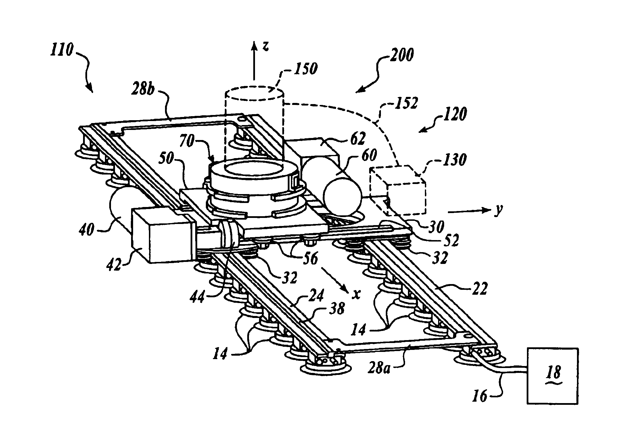
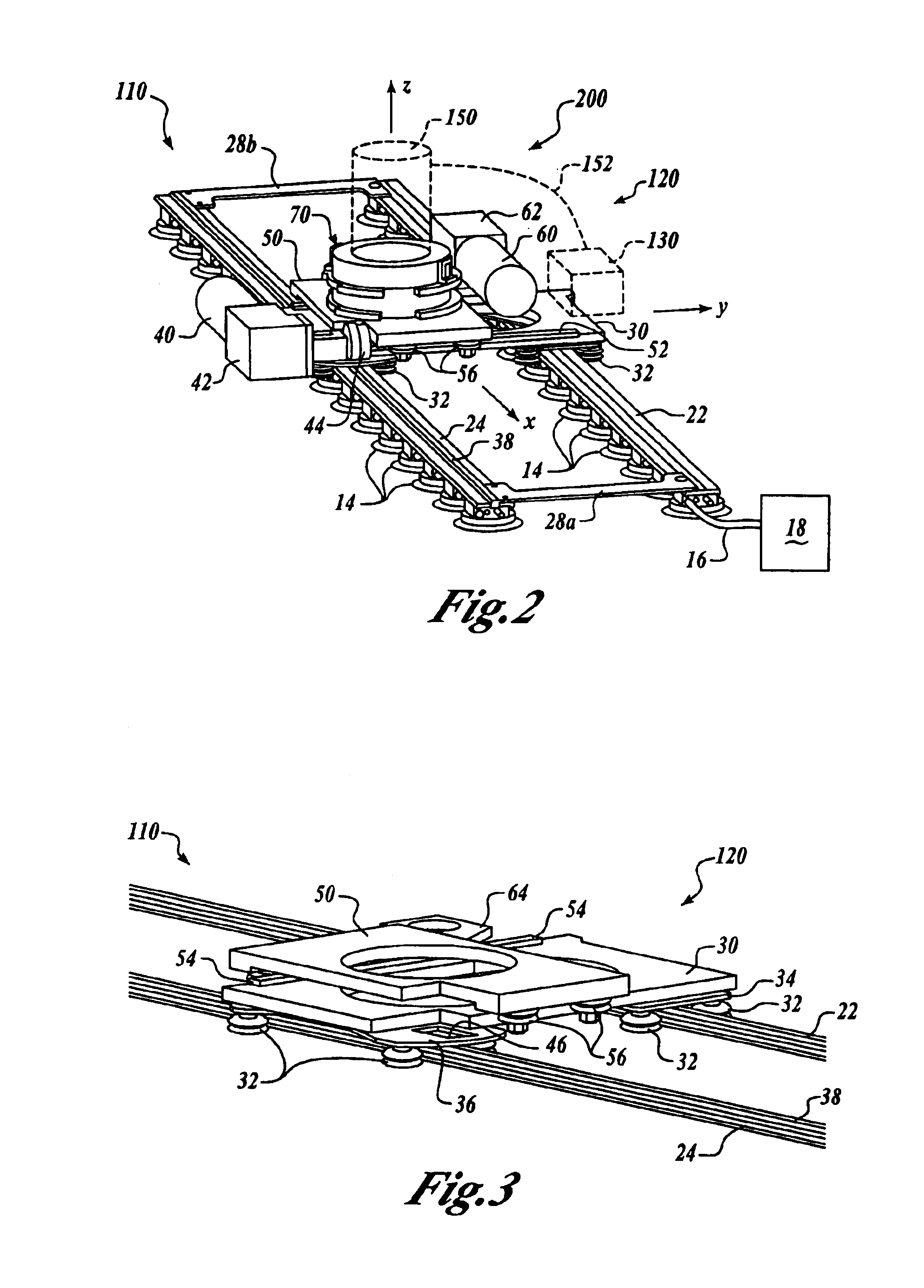
[0008]In one embodiment, an apparatus for performing a manufacturing operation on a workpiece includes a track assembly adapted to be attached to the workpiece, a carriage assembly moveably coupled to the track assembly and moveable relative to the workpiece, and a position sensor. The position sensor is operatively coupled to the carriage assembly and includes a sensor element adapted to be operatively positioned relative to the workpiece. The sensor element is further adapted to detect at least one edge of an index feature on the workpiece from a distance away from the index feature. Because the sensor element detects an edge of the index feature from a distance away from the index feature, the sensor element advantageously does not physically contact the index feature, and may therefore provide improved reliability and maintainability in comparison with prior art systems.
[0009]In another embodiment, an apparatus for performing a manufacturing operation on a workpiece includes a track assembly adapted to be attached to the workpiece, a carriage assembly moveably coupled to the track assembly and moveable relative to the workpiece, and a position sensor operatively coupled to the carriage assembly. The position sensor includes a sensor element adapted to be operatively positioned relative to the workpiece, and a sensing circuit having a first portion coupled to the sensing element, the first portion being adapted to receive an analog input signal and provide a conditioned analog output signal on a first output node. The sensing circuit further includes a second portion coupled to the first portion and adapted to receive the conditioned analog output signal and to provide a digital output signal on a second output node. Thus, the sensor element advantageously provides both analog and digital output signals to the relevant controller apparatus, thereby improving the versatility and accuracy of the manufacturing system.
[0010]In a further embodiment, an apparatus for performing a manufacturing operation on a workpiece including a track assembly adapted to be attached to the workpiece, a carriage assembly moveably coupled to the track assembly and including a drive assembly operable to translate the carriage assembly along the track assembly, and a controller mounted on the carriage assembly and operatively coupled to the drive assembly. The controller is adapted to transmit control signals to the drive assembly to control movement of the carriage assembly over the workpiece. Because the controller is mounted on the carriage assembly, the carriage assembly may operate autonomously to perform manufacturing operations on the workpiece, and the amount of support equipment may be reduced.

Problems solved by technology

Such physical contacts may be subject to degradation, especially through repeated usage, and may also adversely impact the quality of some types of workpiece surfaces.
Although desirable results have been achieved using such manufacturing assemblies, the extent of movement of the support carriage and the operation of the tool assembly may be limited by the lengths of the control cables or by the mobility of the controller within the confines of the manufacturing environment.

Method used


Image

  • Apparatus for manufacturing operations using non-contact position sensing
  • Apparatus for manufacturing operations using non-contact position sensing
  • Apparatus for manufacturing operations using non-contact position sensing

Examples


Embodiment Construction

[0024]The present invention relates to apparatus and methods for manufacturing operations using position sensing. Many specific details of certain embodiments of the invention are set forth in the following description and in FIGS. 1-12 to provide a thorough understanding of such embodiments. One skilled in the art, however, will understand that the present invention may have additional embodiments, or that the present invention may be practiced without several of the details described in the following description.

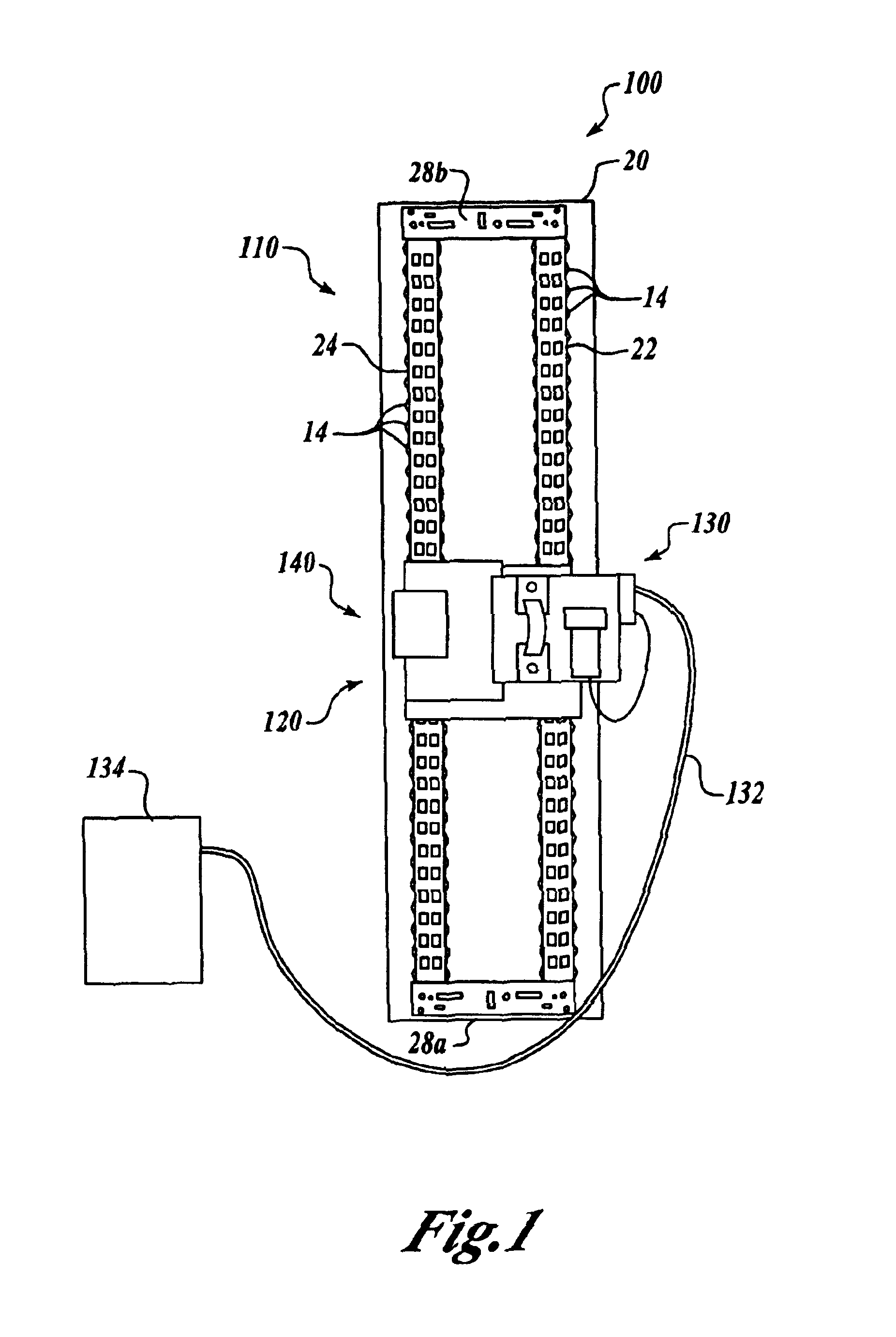
[0025]FIG. 1 is a front elevational view of a manufacturing assembly 100 having a position sensor assembly 140 in accordance with an embodiment of the invention. In this embodiment, the manufacturing assembly 100 includes a track assembly 110 attachable to a workpiece 20, and a carnage assembly 120 moveably coupled to the track assembly 110. A controller 130 is operatively coupled to the position sensor assembly 140 and to the carriage assembly 120. As described more fully...


PUM

PropertyMeasurementUnit
Distanceaaaaaaaaaa
Levelaaaaaaaaaa

Abstract

Apparatus and methods for manufacturing operations using non-contact position sensing are disclosed. In one embodiment, an apparatus includes a track assembly adapted to be attached to a workpiece, a carriage assembly moveably coupled to the track assembly and moveable relative to the workpiece, and a position sensor. The position sensor includes a sensor element adapted to detect at least one edge of an index feature on the workpiece from a distance away from the index feature. In an alternate embodiment, the position sensor may include a sensing circuit that receives an analog signal from the sensing element and provides both analog and digital output signals. In another embodiment, a controller that controls manufacturing operations may be mounted directly on the carriage assembly.

Description

CROSS REFERENCE TO RELATED APPLICATIONS[0001]This patent application is related to co-pending, commonly-owned U.S. patent application Ser. No. 10 / 016,524 entitled “Flexible Track Drilling Machine” filed Dec. 10, 2001, and to the following concurrently-filed, commonly-owned U.S. patent applications: “Methods and Apparatus for Counterbalance-Assisted Manufacturing Operations” bearing Ser. No. 10 / 606,443, “Apparatus and Methods for Manufacturing Operations Using Opposing-Force Support Systems” bearing Ser. No. 10 / 606,472, “Methods and Apparatus for Track Members Having a Neutral-Axis Rack” bearing Ser. No. 10 / 606,625,and “Apparatus and Methods for Servo-Controlled Manufacturing Operations” bearing Ser. No. 10 / 606,402.FIELD OF THE INVENTION[0002]The present disclosure relates to apparatus and methods for manufacturing operations using non-contact position sensing.BACKGROUND OF THE INVENTION[0003]The fabrication of large structures may involve the performance of a large number of manufac...

Claims


Application Information

Patent Timeline
IPC IPC(8): B23Q17/22B23Q9/00B23B39/18
CPCB23B39/18B23Q9/0014B23Q17/22Y10T29/5118Y10T29/49771Y10T29/49764Y10T408/91Y10T29/49828Y10T408/554Y10T409/306384Y10T408/175Y10T408/935
Inventor ARNTSON, PAUL R.OUTOUS, RONALD W.BOYL-DAVIS, THEODORE M.BUTTRICK, JR., JAMES N.
Owner THE BOEING CO
Learn More