Method of setting and actuating a multi-stable micro valve and adjustable micro valve

a multi-stable, micro valve technology, applied in the direction of valve details, wound drains, medical devices, etc., can solve the problems of strong magnetic field, valve misadjustment, and the user does not receive any feedback from the implantant, so as to achieve less sensitive to blockage

Inactive Publication Date: 2005-08-09
MEDOS
View PDF8 Cites 119 Cited by
  • Summary
  • Abstract
  • Description
  • Claims
  • Application Information

AI Technical Summary

Benefits of technology

[0009]The valve object of the present invention overcomes the problems exposed above by providing a micro valve having at least two stable states at operating temperature. The valve according to the invention does not require energy at rest during normal operation and is insensitive to magnetic fields by design. Since the valve setting may be adjusted without mechanical movement of any parts, the valve is less sensitive to blockage due to an accumulation of bio substances.

Problems solved by technology

Nevertheless, there are some drawbacks associated with devices of this type that can be summarized as follows:
These known implants do not provide the user with any feedback during or after adjustment of the valve opening pressure.
Furthermore, the valve can be misadjusted by strong magnetic fields, such as those generated by a permanent magnet found for example in magnetic resonance imaging devices.
Some other known electromechanical or pneumatic valves require energy for remaining in one or more working positions and are not suitable for human or animal implantation due to their size and / or their lack of tightness.

Method used


Image

  • Method of setting and actuating a multi-stable micro valve and adjustable micro valve
  • Method of setting and actuating a multi-stable micro valve and adjustable micro valve
  • Method of setting and actuating a multi-stable micro valve and adjustable micro valve

Examples


first embodiment

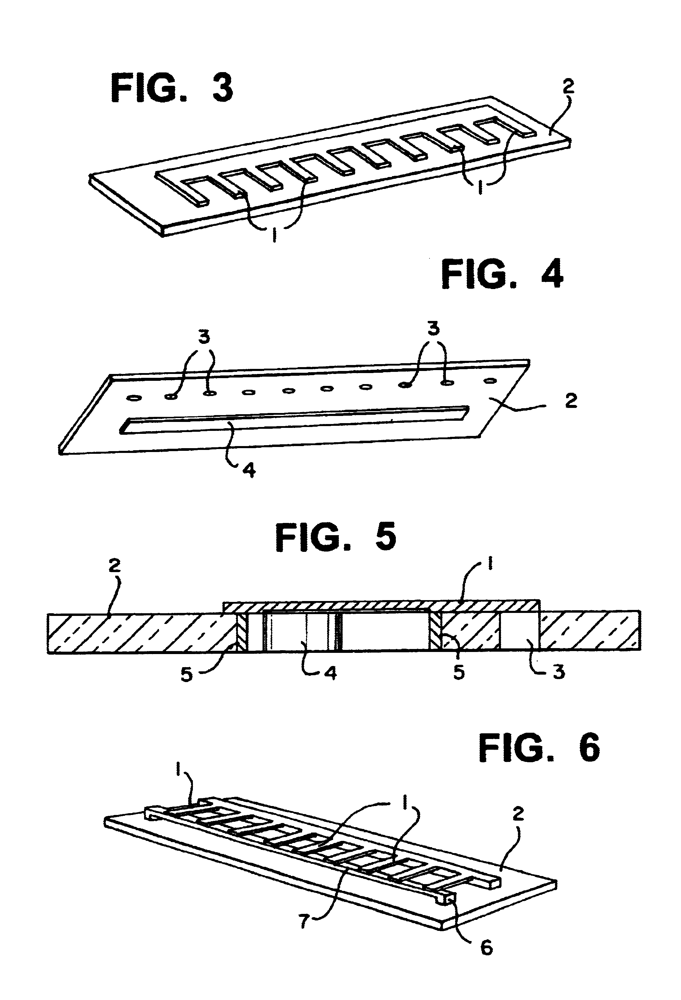
[0040]With reference to FIGS. 3,4 and 5, a micro valve with adjustable opening pressure is illustrated.

[0041]The fluid path crosses a base plate 2 having an array of orifices 3, closed by the free extremity of a corresponding array of actuating members 1. The base plate 2 is preferably made of a glass type material like Pyrex for example. The geometry of the orifices 3 is identical across the array, which ensures that the resistance to fluid is the same for each single orifice 3. The array of actuating members 1 comprises, in this embodiment, an elongated body from which extend perpendicularly elongated actuating members. Some other configurations are of course possible. The actuating members 1 are made of SMA material, preferably TiNi, and their geometry is chosen so that each fluid path 3 can be considered as closed when the corresponding actuating member 1 is in the austenitic state and open in the martensitic state.

[0042]A Peltier cell 4 is integrated in the base plate 2, and al...

third embodiment

[0050]With reference to FIGS. 9 and 10, a valve according to the invention is disclosed. This embodiment provides a valve with an adjustable resistance to flow. A circular base plate 9 comprises, on its periphery, an array of openings 10 through which a fluid may flow. An array of actuating members 11 is arranged on the base plate 9 so that the free end of each actuating member 11 closes a corresponding opening 10 of the base plate. The SMA actuating members 11 are preferably extending from the center of the base plate 9 to the periphery of the plate.

[0051]In this embodiment, all the actuating members 11 have the same geometry but the geometry of the orifices 10 may differ in order to provide a range of different resistances to flow. A Peltier cell or an array of Peltier cells is integrated in the base plate 9, preferably in the center of the base plate so as to enable cooling of the complete array of SMA actuating members 11.

[0052]The setting or the actuating of the valve is simila...

second embodiment

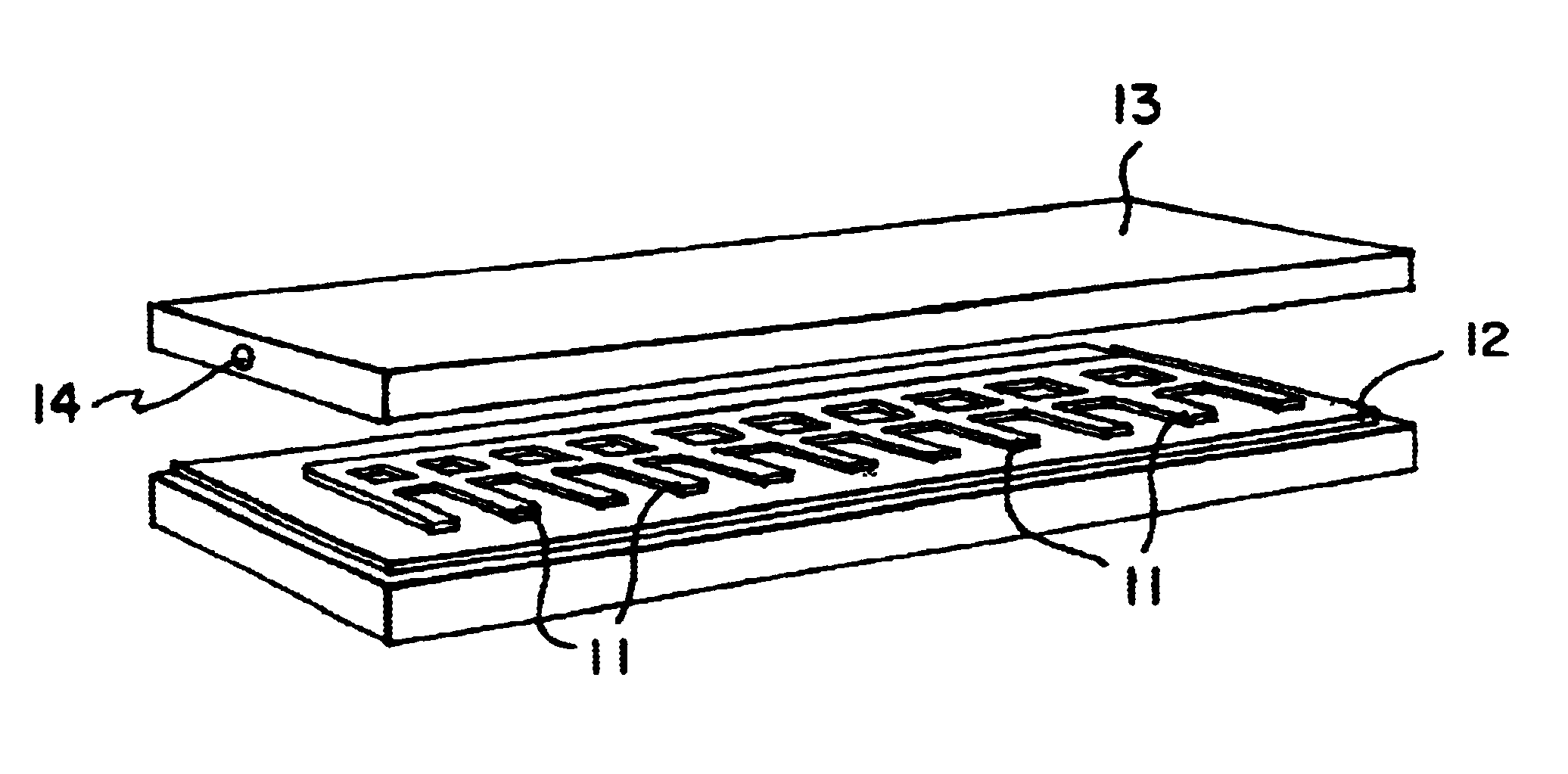
[0053]FIGS. 11, 12 and 13 illustrate an implantable valve with adjustable opening pressure. The implantable valve comprises a valve assembly 12 according to one of the first or second embodiment disclosed above. A top cover 13 having a fluid outlet 14 is adapted to receive the valve assembly 12. An antenna 17 as well as the necessary electronic components 18 to power and control the valve assembly by telemetry are integrated on the bottom of the base plate of the valve assembly 12. A bottom cover 15 having a fluid inlet 16 and a leak tight compartment 19 for protecting the electronic components closes the structure.

[0054]The user may then power the assembly by telemetry and select non-invasively the opening pressure from outside the body by firstly cooling the SMA array of actuating members 11 and then selectively heating by Joule effect one or more actuating members 11. The electronic components 18 integrate a feedback mechanism that can be used to confirm that the correct actuatin...


PUM


Abstract

A micro valve and a method for setting or actuating a micro valve for use in fluidic applications includes cooling an array of actuating members made of Shape Memory Alloy (SMA) material. The SMA material is cooled to a temperature equal to or below the temperature at which a transformation from austenitic to martensitic state occurs so that the entire array of SMA actuating members is either fully or partially in the martensitic state. At least one of the actuating member is selected to correspond to a pre-determined opening pressure or flow resistance. Each of the actuating members are heated individually, except the previously selected one, to a temperature equal to or above the temperature at which a transformation from the martensitic state to the austensitic state occurs.

Description

BACKGROUND OF THE INVENTION[0001]1. Field of the Invention[0002]The present invention relates to a method of setting and / or actuating a multi-stable valve used in fluidic or in micro fluidic applications. Another object of the invention is an adjustable multi stable valve for use in medical devices implanted in a human body.[0003]More specifically, the invention relates to a micro valve having at least two stable states at operating temperature. An opening pressure and a resistance to fluid flow correspond to each state of the valve. The valve may be actuated non-invasively, by telemetry for example, with an external device, providing an adjustable opening pressure valve or alternatively a valve assembly with adjustable resistance to flow.[0004]2. Discussion of the Related Art[0005]The valve object of the present invention has a wide range of applications in different fields (medical, hydraulics, micro-engineering, etc.). For example, in the medical field related to the treatment of...

Claims


Application Information

Patent Timeline
Patent Type & Authority Patents(United States)
IPC IPC(8): A61M27/00F15C5/00F16K31/70F16K31/02F16K99/00
CPCA61M27/006F15C5/00F16K99/0001F16K99/0011F16K99/0036A61M2205/3523F16K2099/0069F16K2099/0088F16K2099/0094Y10T137/6416
Inventor GINGGEN, ALEC
Owner MEDOS
Why Eureka
Try Eureka