
Micro fluidic module

a fluid module and micro-fluidic technology, applied in the direction of positive displacement liquid engines, non-positive displacement pumps, printing, etc., can solve the problems of serious influence on the operating frequency of the ejector, slow refilling, and difficult increase of the channel operating frequency, so as to prevent cross-talk interference, improve the operating frequency of the module, and increase the refilling speed of the working fluid

Inactive Publication Date: 2005-08-09
IND TECH RES INST
View PDF1 Cites 11 Cited by
  • Summary
  • Abstract
  • Description
  • Claims
  • Application Information

AI Technical Summary

Benefits of technology

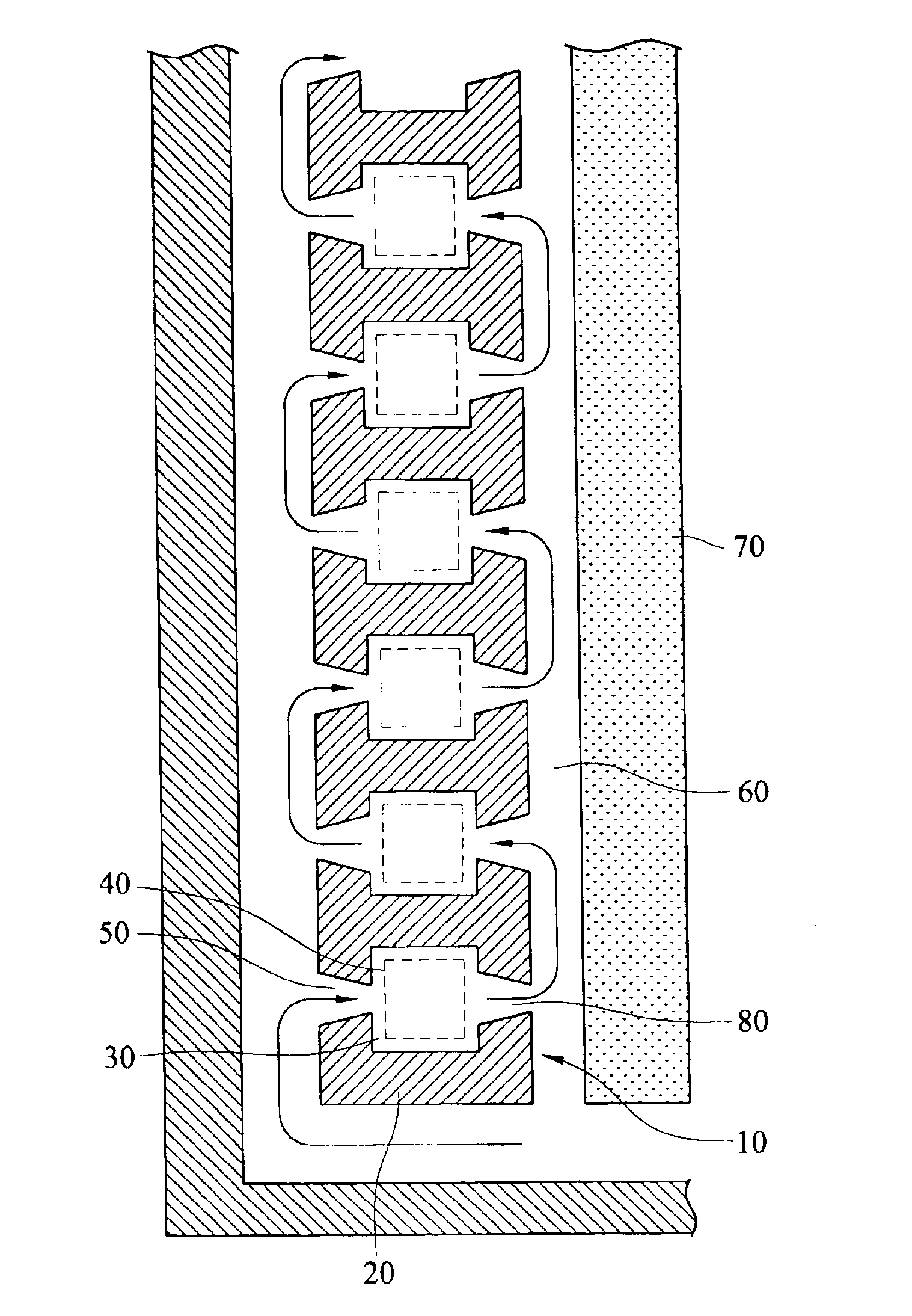
[0010]In the micro fluidic module of the invention, the working fluid in adjacent firing chambers are arranged to have opposite flow directions so that the entire serial micro fluidic units provide an S-shape flow direction. Further, adjacent actuators of the micro fluidic units are driven with different sequences to prevent cross-talk interference of the working fluid. Therefore, the refilling speed of the working fluid is increased, and the operating frequency of the module is improved.
[0011]The convergent micro fluid inlet channel and micro fluid outlet channel in a fluidic module of the invention make the working fluid flow in consistent directions. According to different requirements, the micro fluid channel barrier can be arranged into different shapes; and multiple fluid inlet channels and multiple fluid outlet channels can be used. The variant arrangements provide different kinds of flow directions. In accompany with sequential driving of adjacent actuators of the micro fluid units, the cross-talk of working fluid is prevented. The refilling speed of working fluid and the system operating frequency are increased accordingly.

Problems solved by technology

The operating frequency of the channel is therefore hard to be increased.
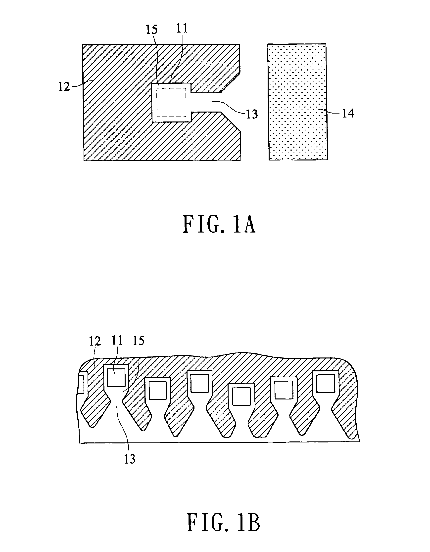
During the ejection process and refilling stage, the flows of working fluid are in opposite directions, the fluidic resistance slows the refilling and seriously influences the operating frequency of the ejector.

Method used


Image

  • Micro fluidic module
  • Micro fluidic module
  • Micro fluidic module

Examples


first embodiment

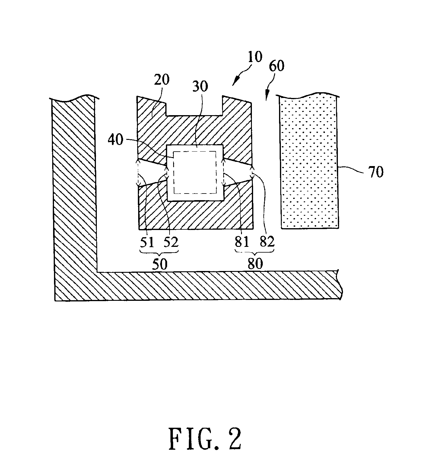
[0024]A micro fluidic channel element 10 as shown in FIG. 2, which composes a micro fluidic module as the invention, includes a micro fluid channel barrier 20 and a firing chamber 30. The firing chamber 30 is formed inside the micro fluid channel barrier 20 for storing working fluid. An activator 40, mounted inside the firing chamber 30, for generating pressure by an electrical input. The activator 40 is usually a piezoelectric ceramic heater for heating the working fluid in the firing chamber 30. Two sides of the micro fluid channel barrier 20 are formed with a fluid inlet channel 50 and a fluid outlet channel 80 respectively. The fluid channels are all of convergent shapes that the left end (front end) 51 of the inlet channel 50 has a wider section, while the right end (rear end) 52 has a narrower section, so as to force working fluid flowing from the front end 51 through the rear end 52. Similarly, the left end (front end) 81 of the outlet channel 80 has a wider section, while th...

second embodiment

[0028]In practice, the convergent shapes of the inlet channels 50 and the outlet channels 80, and the number of channels are not limited. Any arrangement that facilitates the working fluid coming through wider section front ends of channels can be used. For example, FIG. 4 shows the invention. Two sides of the micro fluid channel barrier 20 are formed respectively with two or more convergent fluid inlet channels 50 and two or more convergent fluid outlet channels 80. The multiple outlet channels 80 make the instant high pressure working fluid fast exiting the firing chamber 30. The multiple inlet channels 50 make the lost working fluid in the firing chamber 30 fast refilled from exterior of the channel barrier 20. Therefore, the refilling of working fluid to the firing chamber 30 is easily obtained.

third embodiment

[0029]Further, the positions of fluid inlet channel 50 and fluid outlet channel 80 of the micro fluidic module are not limited to opposite sides of the micro fluid channel barrier 20. As shown in FIG. 5, the invention, a convergent inlet channel 50 is formed on one side of the micro fluid channel barrier 20, while a convergent outlet channel 80 is formed on a side adjacent to the inlet channel 50. So that, the flow direction of working fluid can be arranged to meet different requirements and applications.


PUM


Abstract

A micro fluidic module having at least a micro fluid channel barrier comprises at least an actuator, a firing chamber, a plurality of convergent fluid outlet channel and a plurality of convergent fluid inlet channel. The actuator (e.g. a heater) boils the working fluid and generates thermal bubble and instant high pressure to eject the working fluid outside and expel the working fluid through the fluid outlet channel. Then, the working fluid refills from the fluid inlet channel. Therefore, the working fluid flows consistently through the firing chamber. The working fluid flowing through adjacent firing chambers are arranged in different or consistent directions. Therefore, the refilling speed of the working fluid is increased, and the operating frequency of the module is improved.

Description

[0001]This nonprovisional application claims priority under 35 U.S.C. § 119(a) on Patent Application No(s). 091137908 filed in TAIWAN, R.O.C. on Dec. 30, 2002, which is (are) herein incorporated by reference.BACKGROUND OF THE INVENTION[0002]1. Field of the Invention[0003]The invention generally relates to a micro fluidic module applicable to micro-electromechanical devices, and particularly relates to a micro fluidic module having a consistent fluid flow.[0004]2. Related Art[0005]New technologies are fast developed and greatly facilitate the convenience of modern livings. Developments of micro electromechanical systems are especially a trend of new electronic and mechanical devices. In accompany with developments in semiconductor and information electronic industries, electronic products are getting lighter, thinner, shorter and smaller. The components and manufacturing facilities are also getting more tiny and precise. The manufacturing technologies are aiming at high precision, hi...

Claims


Application Information

Patent Timeline
Patent Type & Authority Patents(United States)
IPC IPC(8): B41J2/14
CPCB41J2/1404B41J2/14145B41J2002/14467
Inventor YANG, JINN-CHERNGMAO, CHING-YIWU, CHOU-LIN
Owner IND TECH RES INST
Learn More