Turbo-molecular pump

a technology of molecular pump and rotor r, which is applied in the direction of liquid fuel engines, machines/engines, combination engines, etc., can solve the problems of rotor r itself damage, vacuum breakage, accidental release of gases in the system to the outside environment, etc., and achieves low friction and facilitate structure.

Inactive Publication Date: 2005-08-09
EBARA CORP
View PDF37 Cites 29 Cited by
  • Summary
  • Abstract
  • Description
  • Claims
  • Application Information

AI Technical Summary

Benefits of technology

[0041]In another aspect of the present invention, turbo-molecular pump may comprise: a rotor; a stator assembly surrounding the rotor; a casing portion surrounding the stator assembly; and a rotation facilitating structure for facilitating rotation of the stator assembly relative to the casing portion when an abnormal torque is applied to the stator assembly from the rotor. Accordingly, since the stator assembly can slide easily within the casing portion, the impact transmitted to the stator assembly is prevented from being transmitted directly to the casing portion, and the energy is absorbed in a sliding process. The rotation facilitating structure may be comprised by a low friction member provided between the stator assembly and casing portion, or a supporting mechanism rotatably supporting the stator assembly.

Problems solved by technology

In such turbo-molecular pumps, abnormal rotation caused by eccentricity of rotor R may sometimes occur, and they may be accompanied by damaging of rotor R itself, especially rotor cylinder section and rotor vanes 30.
Such damage and severing to any parts of stator S cause breakage of vacuum in the whole processing system connected to and evacuated by the pump not only to damage the system facilities and in-process goods, but also to lead to accidental release of gases in the system to outside environment.

Method used


Image

  • Turbo-molecular pump
  • Turbo-molecular pump
  • Turbo-molecular pump

Examples


first embodiment

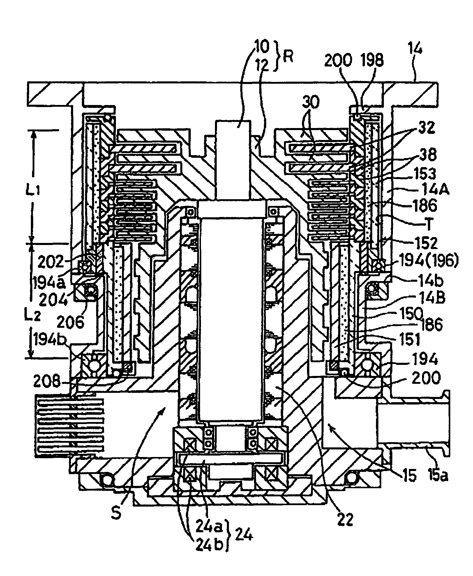
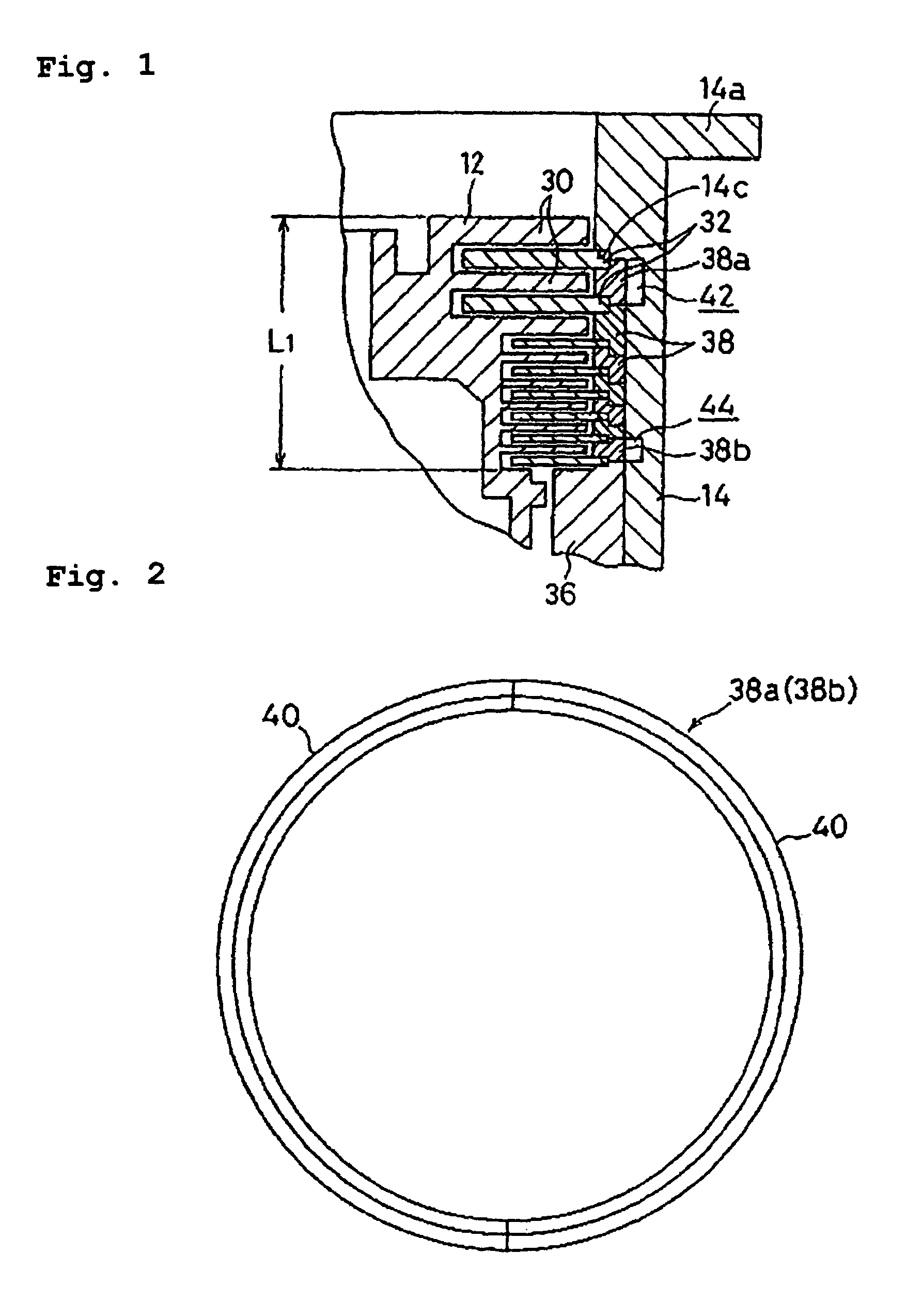
[0080]In the following, preferred embodiments will be presented with reference to the drawings. FIGS. 1 and 2 relate to the turbo-molecular pump. The present pump shares some common structural features with the conventional pump shown in FIG. 37, such as vane pumping section L1 comprised by alternating rotor vanes 30 and stator vanes 32, groove pumping section L2 having spiral groove section 34 and groove pumping section spacer 36. As well, pump casing 14 is used to press down stator vanes 32, stator vane spacers 38 and groove pumping section spacer 36. Therefore, an overall illustration of this embodiment is omitted.

[0081]The present pump is constructed so that, when abnormal torque is applied to the stator vane 32 due to abnormal conditions developing in any rotor components, a part of stator vane spacers 38 is able to move radially outward. This is achieved by having the uppermost vane spacer 38a and the lowermost vane spacer 38b each of which is comprised by vane spacer halves 4...

second embodiment

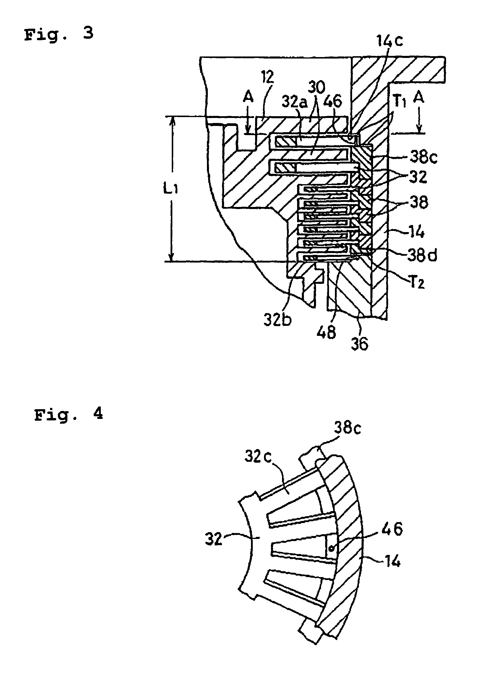
[0085]FIGS. 3 and 4 show the turbo-molecular pump according to the invention. This pump is also constructed so that the axial constrict of stator vane 32 is released at an early stage of the onset of abnormal condition. As shown in FIG. 4, a plurality of support pins 46 are provided equally spaced in the circumferential direction in a space between the vanes 32c of the uppermost stator vane 32a. Similar support pins 48 are also provided in a space between vanes 32b of the lowermost stator vanes 32.

[0086]With reference to FIG. 3, support pins 46 are fitted between step surface 14c of pump casing 14 and the uppermost stator vane spacer 38c as a “support rod”. The length of the pins is chosen to be slightly greater than the thickness of the uppermost stator vane 32a. Similarly support pin 48 is fitted between groove pumping section spacer 36 and the lowermost stator vane spacer 38d and its length is made slightly larger than the thickness of the lowermost stator vane 32b. Therefore, a ...

third embodiment

[0089]FIGS. 5 to 7 show the turbo-molecular pump according to the invention. In this pump, as shown in FIGS. 6 and 7, all stator vane spacers 50, excepting the uppermost stator vane spacer, are provided with a series of threaded holes 50a and bolt holes 50b alternately distributed on the periphery in a circumferential direction so that a bolt (shear bolt) 52 can be inserted through a bolt hole 50b of an upper stator vane spacer 50 to be fastened into a threaded holes 50a of a lower stator vane spacer 50 so as to assemble all stator vane spacers 50 to each other. The lowermost stator vane spacer 50 is fixed to the top of the groove pumping section spacer 54 also by bolts 52.

[0090]The strength of bolts 52 is selected such that, when abnormal torque is transmitted to spacer 50 due to breaking of rotor R or abnormal rotation, they will fracture. The bolt strength is determined either by selecting the material or diameter, or by providing a rupture inducing portion such as a notch on bol...


PUM


Abstract

A turbo-molecular pump of high safety and reliability was presented, so that if an abnormal condition should develop on the rotor side, it will not lead to any damage to the stationary portions such as the stator or pump casing to cause loss of vacuum in a vacuum processing system. The turbo-molecular pump includes a rotor; a stator assembly surrounding the rotor; and a casing portion surrounding the stator assembly, wherein at least a partial clearance is formed between the stator assembly and the casing portion, so that, when an abnormal torque is applied from the rotor to the stator assembly, direct impact transmission is prevented from the stator assembly to the casing portion.

Description

[0001]This is a continuation-in-part of U.S. patent application Ser. No. 09 / 104,171, filed Jun. 25, 1998, now issued as U.S. Pat. No. 6,332,752.BACKGROUND OF THE INVENTION[0002]1. Field of the Invention[0003]The present invention relates to a turbo-molecular pump for evacuating gas by using a high speed rotor.[0004]2. Description of the Related Art[0005]An example of a conventional turbo-molecular pump is shown in FIG. 37. The turbo-molecular pump is comprised by a cylindrical pump casing 14 housing a vane pumping section L1 and a groove pumping section L2 which are constituted by a rotor (rotation member) R and a stator (stationary member) S. The bottom portion of pump casing 14 is covered by a base section 15 which is provided with an exhaust port 15a. The top portion of pump casing 14 is provided with a flange section 14a for coupling the pump to an apparatus or a piping to be evacuated. Stator S comprises a stator cylinder section 16 provided upright at the center of the base se...

Claims


Application Information

Patent Timeline
Patent Type & Authority Patents(United States)
IPC IPC(8): F04D27/02F04D19/00F04D19/04
CPCF04D19/042F04D29/522F04D29/701F04D27/0292
Inventor MIYAMOTO, MATSUTAROOGAMINO, HIROAKIIKEGAMI, TETSUMAKAWASAKI, HIROYUKI
Owner EBARA CORP
Why Eureka
Try Eureka