
Eureka
For R&D, Eureka makes reading and utilizing patents & technical documents easy.
Eureka AIR
Designed for self-driven R&D workflows. Generate viable solutions, solve complex R&D challenges, empower your innovation with AI.

Eureka Materials
Designed for material experts only. Revolutionize your material R&D, from search, analyze, to developing new materials.

TechResearch
Generate reliable direction feasibility study reports for your R&D in just a few steps.

TechSeek
Discover and master advanced knowledge NOW. Basics, ideas, possibilities, all at once.

TechMind
As an expert in R&D Theories, TechMind can generates customized viable solutions instantly.

TechRisk
Analyze your overall solution with one click, know your potential R&D risks in advance.

TechMonitor
Get weekly tech updates, stay abreast of the latest tech innovations and key insights.
Gaming machine
- Summary
- Abstract
- Description
- Claims
- Application Information
AI Technical Summary
Benefits of technology
Problems solved by technology
Method used
Image

Examples
first embodiment
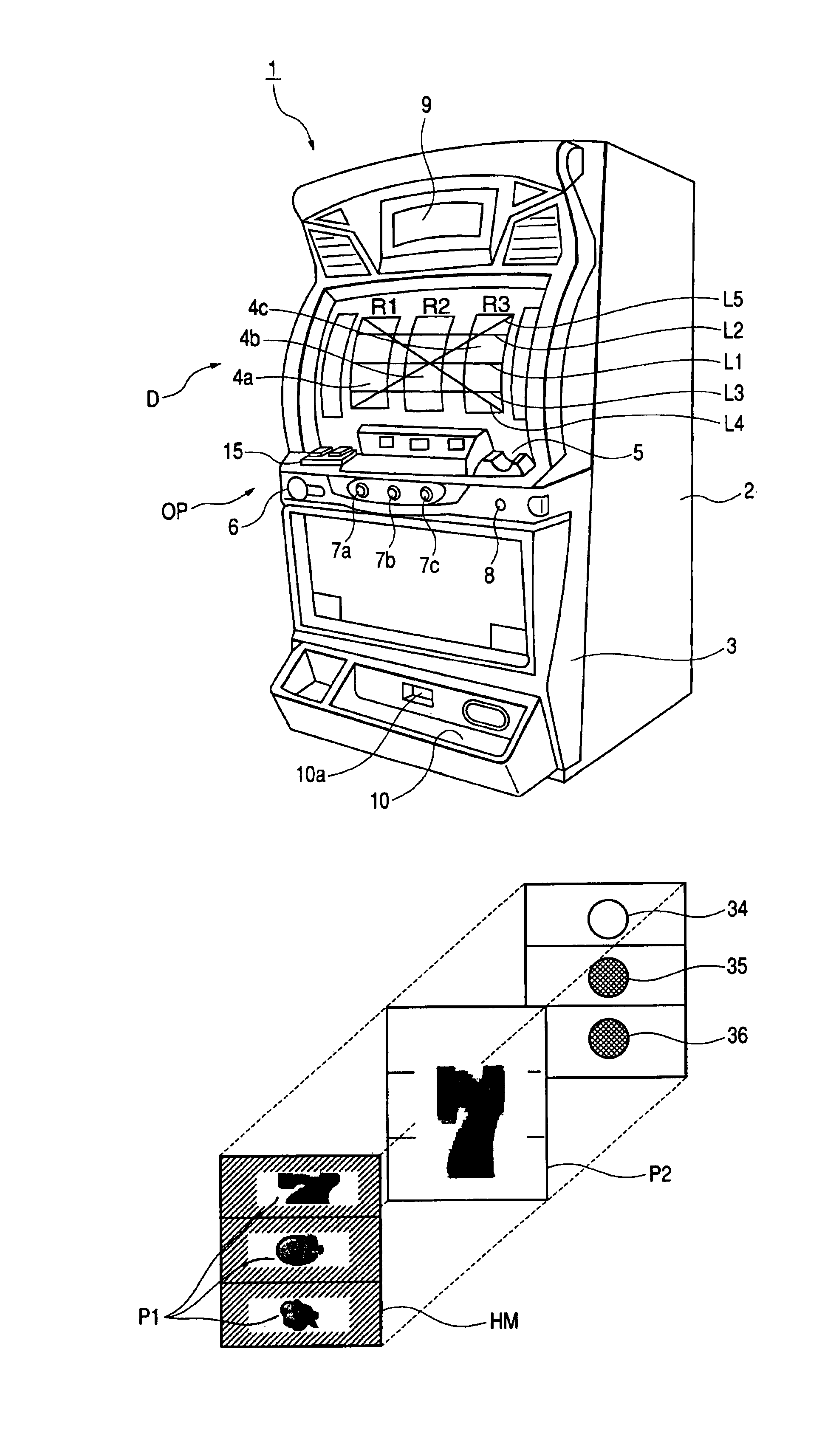
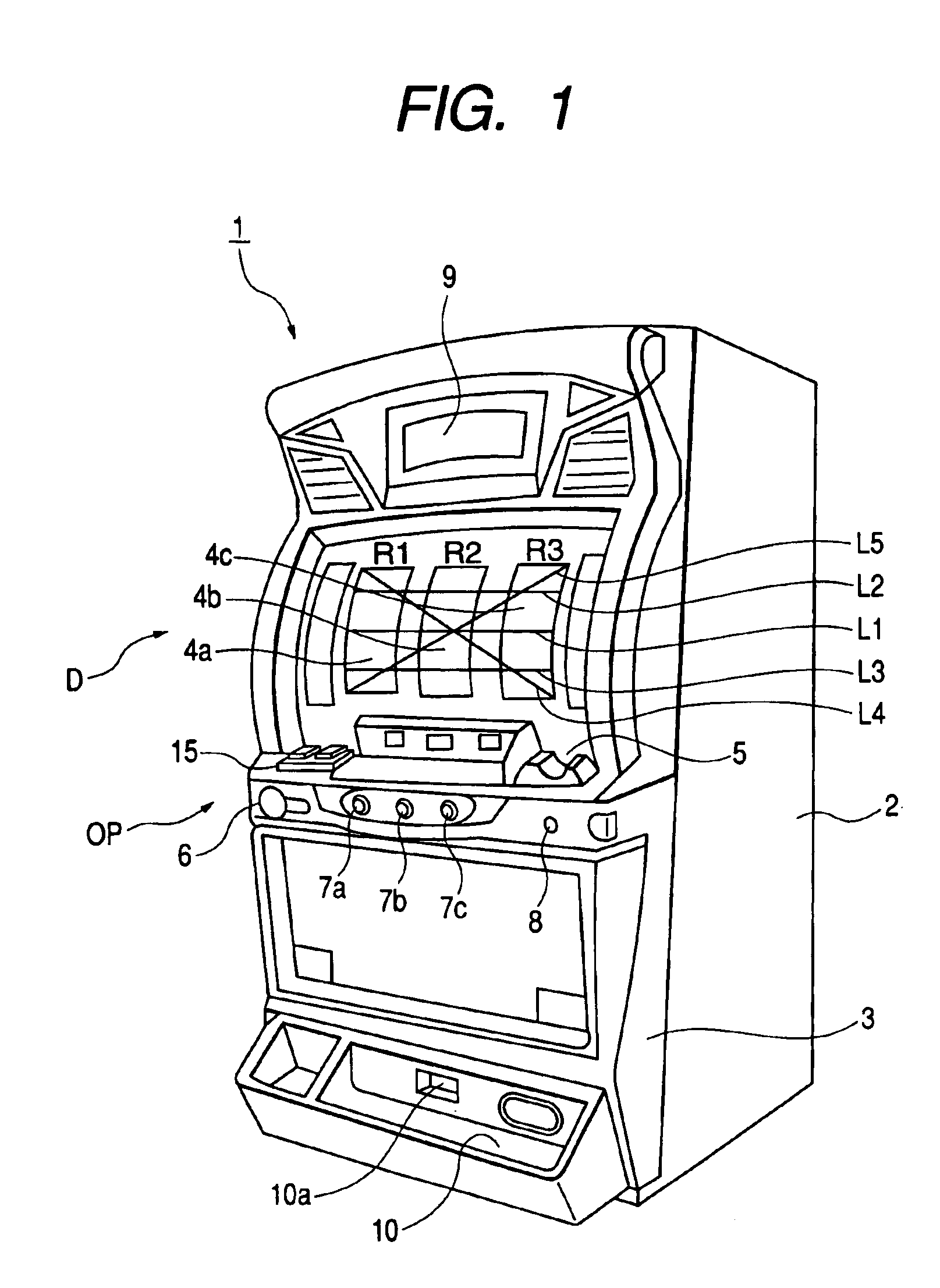
[0051]FIG. 1 is a perspective view showing the external appearance of a slot machine 1 according to the invention. A housing of the slot machine 1 has a main unit 2, and a front door 3 attached to the front of the main unit 2. A liquid-crystal display device 9 for providing a player with predetermined information is arranged at an upper portion of the front door 3. A panel display section D disposed at a middle portion of the front door 3 has three horizontally-oriented rectangular display windows 4a, 4b, and 4c. Three horizontal pay lines L1 through L3 and two sloped pay lines L4 and L5 are provided across the display windows 4a, 4b, and 4c. Three reels, on whose outer peripheral faces a plurality of kinds of symbols are drawn; that is, a left reel R1, a center reel R2, and a right reel R3, are rotatably disposed at the inside of the panel display section D. The display windows 4a, 4b, and 4c are formed from transparent material; e.g., acrylic resin. Accordingly, the player can obs...
second embodiment
[0066]the invention will be described with reference to FIGS. 5E to 5G.
[0067]According to the structure shown in FIG. 5E, an auxiliary print layer P1, the half mirror layer HM, the base film layer B, a primary print layer P2 are arranged in this order from the player. According to the structure shown in FIG. 5F, the auxiliary print layer P1, the base film layer B, the half mirror layer HM, the primary print layer P2 are arranged in this sequence from the player. According to the structure shown in FIG. 5G, the base film layer B, the auxiliary print layer P1, the half mirror layer HM, the primary print layer P2 are arranged in this sequence from the player. In all of these layer structures shown in FIGS. 5E to 5G, the print layers P1, P2 are disposed at both the inside and the outside of the half mirror layer HM.
[0068]Accordingly, when the white cold-cathode tube remains inactive, the player simultaneously views the symbol located on the half mirror layer HM and the external light re...
third embodiment
[0069]the invention will be described with reference to FIG. 5H. In this embodiment, the half mirror HM is formed on another translucent film TF and adhered to the print layer P provided on the base film layer B with an adhesive layer AD. Since the half mirror layer HM is not exposed to the outside, the half mirror layer is easy to handle and less susceptible to time-varying changes.
[0070]Display of symbols to be performed by the half mirror layer HM and the print layer P will be described more specifically. In the following explanations, a position close to the viewer corresponds to the lower side of the drawings, and a position distant from the viewer corresponds to the upper side of the drawings.
PUM
 Abstract
Description
Claims
Application Information
 - R&D Engineer
- R&D Manager
- IP Professional
- Industry Leading Data Capabilities
- Powerful AI technology
- Patent DNA Extraction
Browse by: Latest US Patents, China's latest patents, Technical Efficacy Thesaurus, Application Domain, Technology Topic, Popular Technical Reports.
© 2024 PatSnap. All rights reserved.Legal|Privacy policy|Modern Slavery Act Transparency Statement|Sitemap|About US| Contact US: help@patsnap.com