Cell plate structure for solid electrolyte fuel cell, solid electrolyte fuel cell and related manufacturing method

a technology of solid electrolyte fuel cell and cell plate structure, which is applied in the manufacture of final products, cell components, electrochemical generators, etc., can solve problems such as loss of electric power generating outpu

Inactive Publication Date: 2005-08-09
NISSAN MOTOR CO LTD
View PDF6 Cites 22 Cited by
  • Summary
  • Abstract
  • Description
  • Claims
  • Application Information

AI Technical Summary

Benefits of technology

[0012]The present invention has been completed upon considerable research and development work conducted by the present inventors, in view of the above studies, based on a newly obtained knowledge as to such a step in which especially, when forming at least one of electrode layers, a substance to be removed in a post-treatment is contained in the at least one of electrode layers and then the included substance is removed from the at least one of electrolyte layers in the post-treatment. It is therefore an object of the present invention to provide a cell plate structure for an SOFC (hereinafter p

Problems solved by technology

For instance, the presence of a leakage of fuel gas and air even in a small amount due to a pin hole formed in the electr

Method used


Image

  • Cell plate structure for solid electrolyte fuel cell, solid electrolyte fuel cell and related manufacturing method
  • Cell plate structure for solid electrolyte fuel cell, solid electrolyte fuel cell and related manufacturing method
  • Cell plate structure for solid electrolyte fuel cell, solid electrolyte fuel cell and related manufacturing method

Examples


first preferred embodiment

(First Preferred Embodiment)

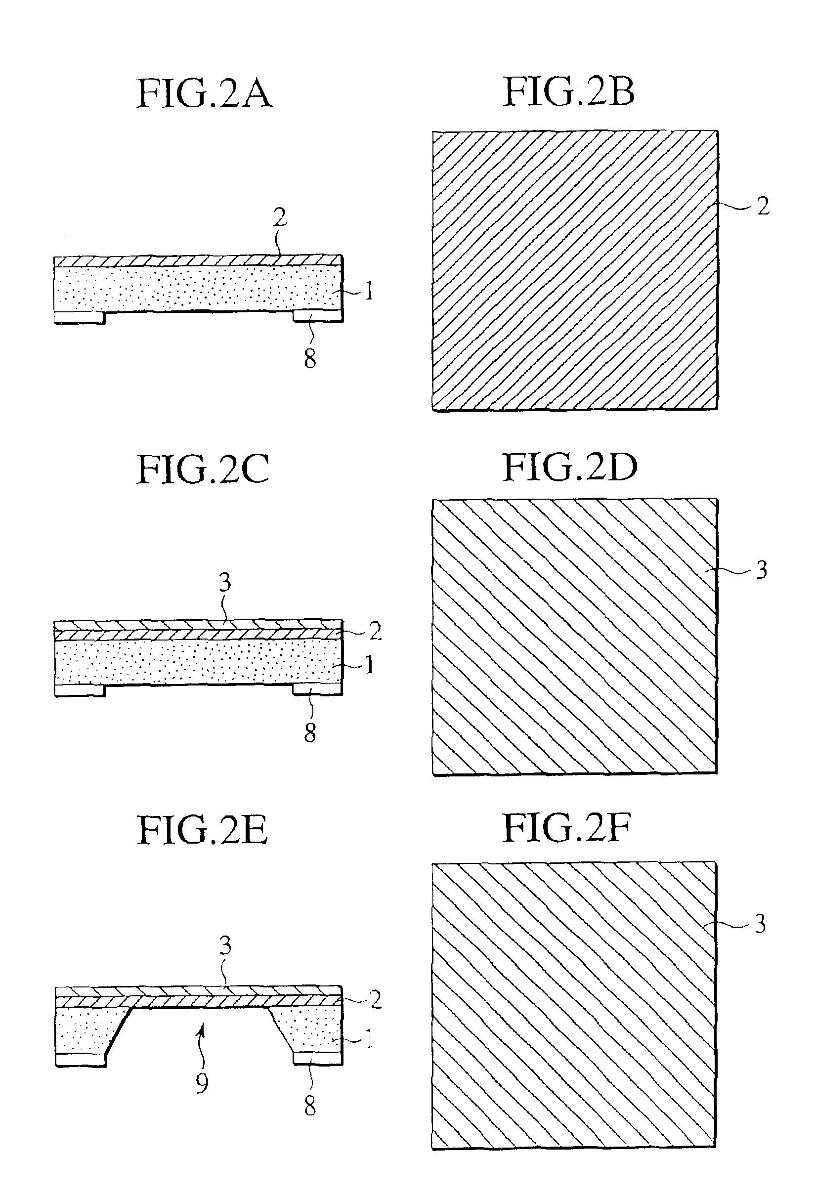
[0029]First, an SOFC cell plate structure, its related manufacturing method, an SOFC using such an SOFC cell plate structure and its related manufacturing method of a first preferred embodiment according to the present invention are successively described below in detail with reference to FIGS. 1A to 5.

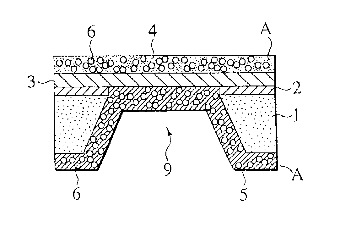
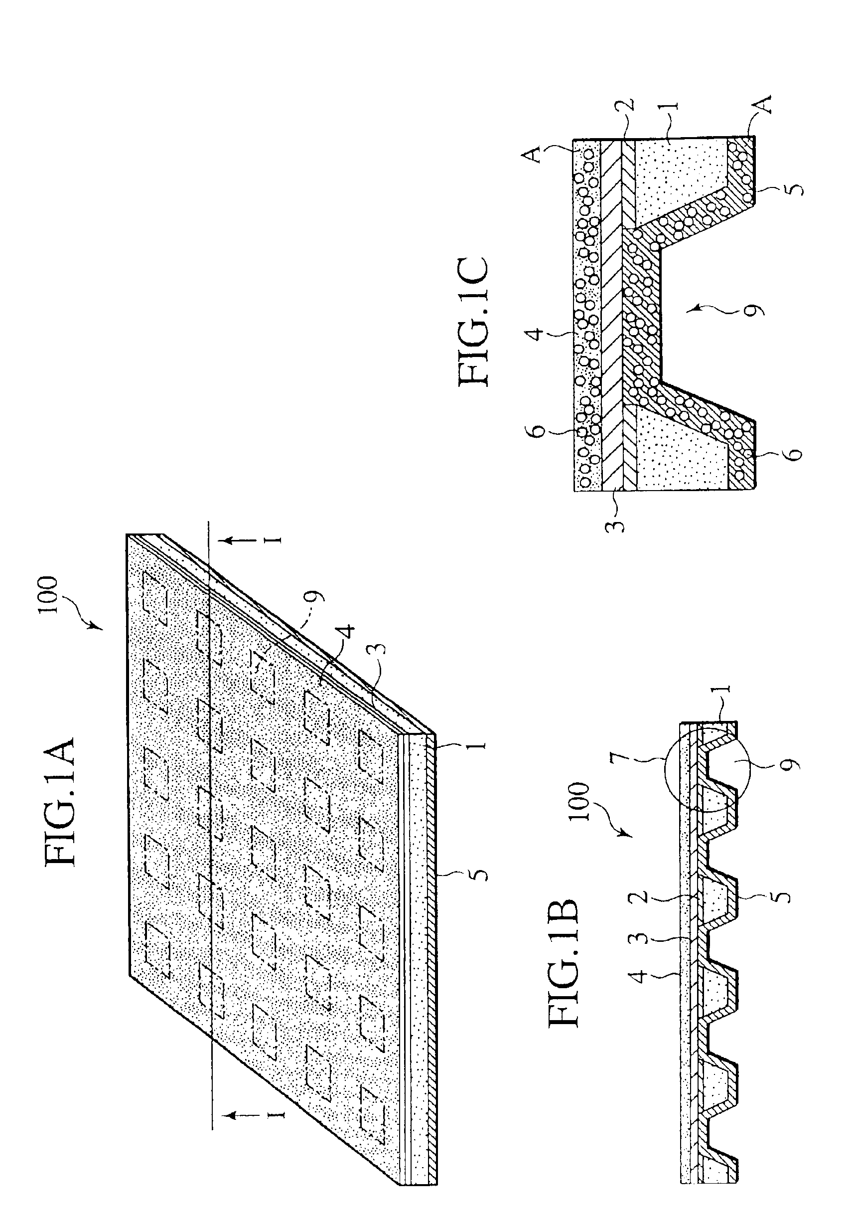
[0030]FIG. 1A is a schematic perspective view showing an external structure of the SOFC cell plate structure of the preferred embodiment, FIG. 1B is a cross sectional view taken on line I—I of FIG. 1A, and FIG. 1C is an enlarged cross sectional view illustrating a cell portion, shown in FIG. 1B, in an enlarged scale.

[0031]As shown in FIGS. 1A to 1C, the SOFC cell plate structure 100 is comprised of a silicon substrate 1 formed in a square shape with the width of 10 cm, with cell portions 7 each having an opening formed in a square shape with the width of approximately 5 mm being formed in 5×5 pieces.

[0032]In particular, the silicon substrate 1 has a surface...

second preferred embodiment

(Second Preferred Embodiment)

[0057]Now, an SOFC cell plate structure, its related manufacturing method, an SOFC using such an SOFC cell plate structure and its related manufacturing method of a second preferred embodiment according to the present invention are described below in detail with reference to FIGS. 6A to 7D.

[0058]Fundamentally, since the second preferred embodiment has the same structure as the first preferred embodiment except for that all of the lower electrode layer 5, the electrolyte layer 3 and the upper electrode layer 4 are preliminarily laminated on the diaphragm composed of the silicon nitride film serving as the insulation layer 2, the layers of component part of the SOFC are laminated in a different order, with a substance to be contained in the upper electrode layer 4 and the lower electrode layer 5 once and arranged to contain silicon nitride that is different from the substance to be contained once in the electrode layers of the first preferred embodiment. C...

third preferred embodiment

(Third Preferred Embodiment)

[0072]Now, an SOFC cell plate structure, its related manufacturing method, an SOFC using such an SOFC cell plate structure and its related manufacturing method of a third preferred embodiment according to the present invention are described below in order with reference to FIGS. 8A to 8F.

[0073]Fundamentally, the third preferred embodiment has the same structure as the first preferred embodiment except for that all of the lower electrode layer 5, the electrolyte layer 3 and the upper electrode layer 4 are laminated on a silicon substrate 1 and subsequently the silicon substrate 1 is etched by silicon etching liquid to form pores 6 in the upper electrode layer 4 and the lower electrode layer 5, and that layers of the component parts of the SOFC are laminated in a different order and the pores 6 of the upper electrode layer 4 and the lower electrode layer 5 are formed in a different step. Consequently, the third preferred embodiment is described below in a s...


PUM

PropertyMeasurementUnit
Thicknessaaaaaaaaaa
Particle sizeaaaaaaaaaa

Abstract

A cell plate structure for a solid oxide electrolyte type fuel cell is provided with a lower electrode layer, an upper electrode layer provided in opposition to the lower electrode layer, a solid electrolyte layer provided between the lower electrode layer and the upper electrode layer, and an area provided in at least one of the lower electrode layer and the upper electrode layer. The area has a portion which is formed by removing a substance, contained in the at least one of the lower electrode layer and the upper electrode layer during formation thereof, after the at least one of the lower electrode layer and the upper electrode layer has been formed. Such a fuel cell plate structure can be applied to a solid electrolyte fuel cell representatively by being disposed between a pair of separators that have gas flow passages supplying the lower electrode layer and the upper electrode layer with gasses, respectively.

Description

BACKGROUND OF THE INVENTION[0001]The present invention relates to a cell plate structure for a solid electrolyte fuel cell, a solid electrolyte fuel cell and a related manufacturing method thereof and, more particularly, to a cell plate structure for a solid electrolyte fuel cell, which uses a solid electrolyte to obtain electrical energy due to an electro-chemical reaction, a solid electrolyte fuel cell using such a cell plate structure and a related manufacturing method thereof.[0002]In recent years, a great attention has heretofore been focused on fuel cells as clean energy sources that generate electric power output at a high energy conversion efficiency to be friendly in an earth environment.[0003]Among these fuel cells, a solid oxide electrolyte type fuel cell (solid oxide fuel cell: hereinafter referred to as SOFC) employs electrolyte composed of an oxide ion conductivity type solid electrolyte such as yttria-stabilized zirconia.[0004]In such an SOFC, it is proposed that both...

Claims


Application Information

Patent Timeline
IPC IPC(8): H01M8/12H01M4/88H01M4/86H01M8/02
CPCH01M8/1213H01M8/122H01M8/1226H01M8/124H01M8/1286Y02E60/521Y02E60/525H01M4/881H01M4/8878H01M4/8889Y02E60/50Y02P70/50
Inventor SATOU, FUMINORIYAMANAKA, MITSUGUUCHIYAMA, MAKOTOHATANO, MASAHARUKUSHIBIKI, KEIKOHARA, NAOKIFUKUZAWA, TATSUHIROSHIBATA, ITARU
Owner NISSAN MOTOR CO LTD
Why Eureka
Try Eureka