Bypass arrangement for low-noise amplifier

a low-noise amplifier and bypass path technology, applied in gated amplifiers, amplification control details, electrical devices, etc., can solve the problems of reducing and reducing the efficiency of the front stage, so as to simplify the front stage structure, improve the noise figure of the front stage of the receiver, and improve the isolation effect of the lna bypass path

Active Publication Date: 2005-08-09
INTEL CORP
View PDF4 Cites 58 Cited by
  • Summary
  • Abstract
  • Description
  • Claims
  • Application Information

AI Technical Summary

Benefits of technology

[0007]An advantage of the invention is that the noise figure of the receiver front stage will be improved. This is a result of the fact that, first, the series switch on the signal path, which most degrades the noise figure,

Problems solved by technology

Another disadvantage caused by the switches is that in the normal operating mode of the receiver the isolation on the LNA bypass path is finite, not infinite.
T

Method used


Image

  • Bypass arrangement for low-noise amplifier
  • Bypass arrangement for low-noise amplifier
  • Bypass arrangement for low-noise amplifier

Examples


Embodiment Construction

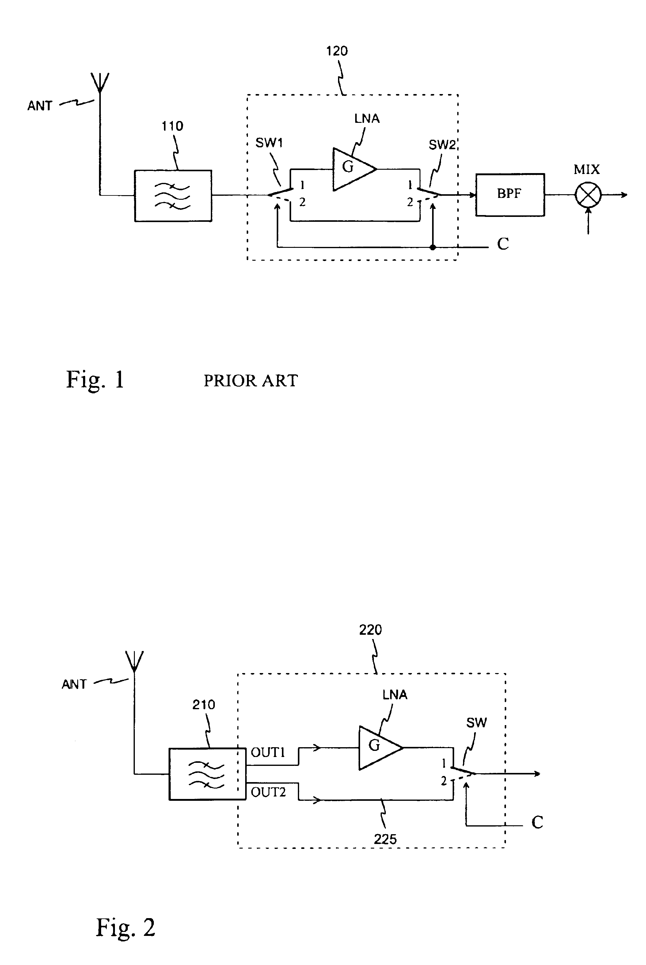
[0013]FIG. 1 was already discussed in connection with the description of the prior art.

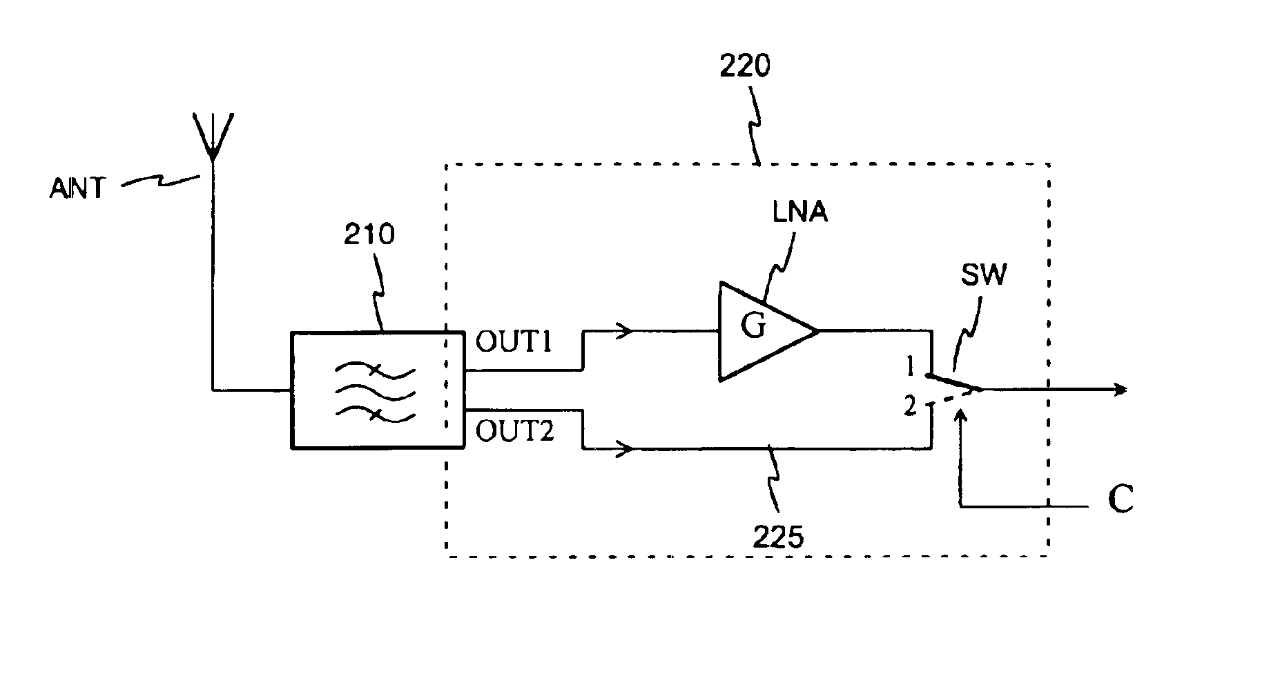
[0014]FIG. 2 is a block diagram illustrating the principle of the LNA bypass arrangement according to the invention. FIG. 2 shows an antenna ANT connected to receiver's antenna filter 210. In accordance with the invention the antenna filter has two parallel outputs: a first output OUT1 and a second output OUT2. The first output is connected direct to the input of a low-noise amplifier LNA, and the second output is connected direct to the LNA bypass path 225. Here and in the claims the phrase “connected direct” refers to a connection between circuit portions that cannot be changed by electric control. Next on the signal path there is a changeover switch SW, like the changeover switch SW2 in FIG. 1. The output of the LNA is connected to a first changeover terminal in the changeover switch SW, and the bypass path 225 is connected to a second changeover terminal of the changeover switch SW. By means o...


PUM


Abstract

An arrangement for bypassing a low-noise amplifier (LNA), intended especially to be used in base stations of mobile networks. For the bypass, a receiver antenna filter (210) has a second output (OUT2) parallel with a first output (OUT1) connected to the LNA. The antenna filter is of the resonator type, and there is a conductive element for each of its outputs in the resonator cavity. Selection between the LNA out-put signal and signal coming direct from the antenna filter is made by a changeover switch (SW). The noise figure of the receiver front stage (220) will improve as the series switch on the signal path, which most degrades the noise figure, is removed between the filter and LNA, and isolation on the LNA bypass path increases.

Description

[0001]The invention relates to an arrangement for bypassing a low-noise amplifier in a radio receiver. The arrangement finds particular utility in base stations of mobile communication networks.BACKGROUND OF THE INVENTION[0002]In all radio receivers, the first amplifier on the path from the antenna into the receiver should have very low noise characteristics, for the signal level at the input of this amplifier is low and additional noise caused by the amplifier will be amplified in all amplifier stages to follow. A low-noise first amplifier is usually abbreviated LNA. In receivers of mobile network base stations the maximum allowable noise figure specified for the LNA is typically 1.8 dB. This is a relatively strict requirement especially considering that the figure includes the increase in the noise figure caused by a circuit arrangement enabling bypassing of the LNA. The LNA needs to be bypassed because of certain base station maintenance measurements and in LNA fault conditions.[...

Claims


Application Information

Patent Timeline
IPC IPC(8): H03G1/00H04B1/18
CPCH03F3/72H03G1/0088H04B1/18
Inventor NIEMI, MIKA
Owner INTEL CORP
Why Eureka
Try Eureka