Motion estimation method using multilevel successive elimination algorithm
- Summary
- Abstract
- Description
- Claims
- Application Information
AI Technical Summary
Benefits of technology
Problems solved by technology
Method used
Image

Examples
Embodiment Construction
[0040]The above and other objects and features of the instant invention will become apparent from the following description of preferred embodiments taken in conjunction with the accompanying drawings.
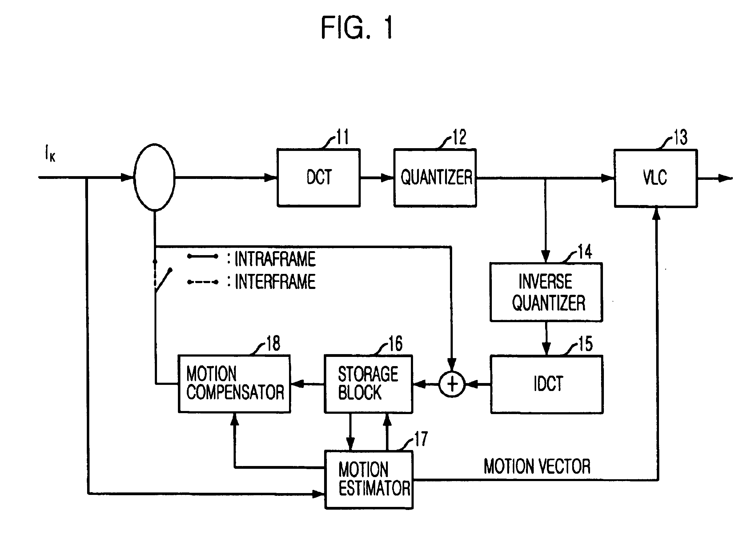
[0041]FIG. 1 is a block diagram for explaining a moving image compression system employing the inventive method in accordance with a preferred embodiment of the present invention.
[0042]As shown in FIG. 1, the moving image compression system employing the invention comprises a discrete cosine transformer (DCT) 11, a quantizer 12, a variable length coder (VLC) 13, an inverse quantizer 14, an inverse DCT (IDCT) 15, a storage block 16, a motion estimator 17, and a motion compensator 18.
[0043]The DCT 11 converts an image signal from a spatial domain to a frequency domain on a block-by-block basis of 8×8 pixels to provide a set of DCT transform coefficients, thereby eliminating spatial redundancies by using correlations in the image signal. Conventionally, since variance of the image data is...
PUM
 Abstract
Description
Claims
Application Information