Method and apparatus for compensating local oscillator frequency error

a local oscillator and frequency error technology, applied in the field of electromechanical circuits, can solve the problems of limiting the actual application of the local oscillator in the electronic system, the absence of tuning range, and the extreme frequency accuracy of the local oscillator. the effect of reducing the frequency error

Inactive Publication Date: 2005-08-09
QUALCOMM INC
View PDF33 Cites 66 Cited by
  • Summary
  • Abstract
  • Description
  • Claims
  • Application Information

AI Technical Summary

Benefits of technology

[0018]The present invention is a novel and improved method and apparatus for reducing the frequency error of a Local Oscillato

Problems solved by technology

Atomic clocks exhibit extreme levels of frequency accuracy, however, their size, cost, and absence of tuning range greatly limit their actual application within an electronic system.
The main problem in a GPS implementation is the accurate determination of the distance from the satellite to the receiver.
However, the mobile receiver is only weakly synchronized to the satellites.
The weak time synchronization of the receiver to the satellites introduces errors into the position determination.
Therefore, the timing error from the receiver to one satellite is the same as the timing error from the receiver to any of the satellites in the constellation.
Resolution of the timing error is only one of the problems that must be dealt with when position determination using GPS is implemented.
The size and cost constraints become increasingly important when the GPS receiver is implemented in a consumer oriented device.
Yet, despite the physical design constraints, the receiver must quickly search and acquire the satellite signals.
A receiver design cannot maximize all parameters si

Method used


Image

  • Method and apparatus for compensating local oscillator frequency error
  • Method and apparatus for compensating local oscillator frequency error
  • Method and apparatus for compensating local oscillator frequency error

Examples


Embodiment Construction

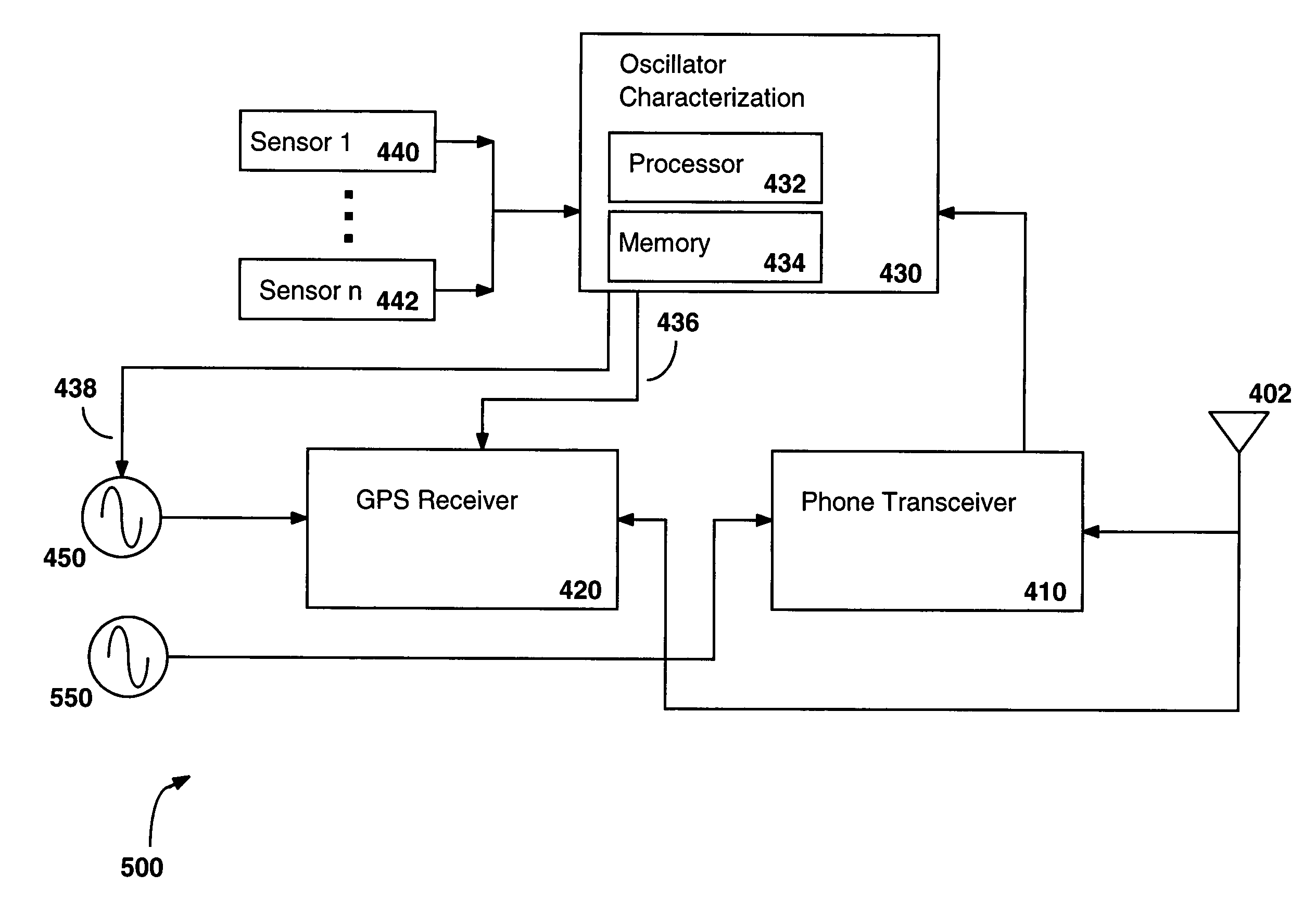
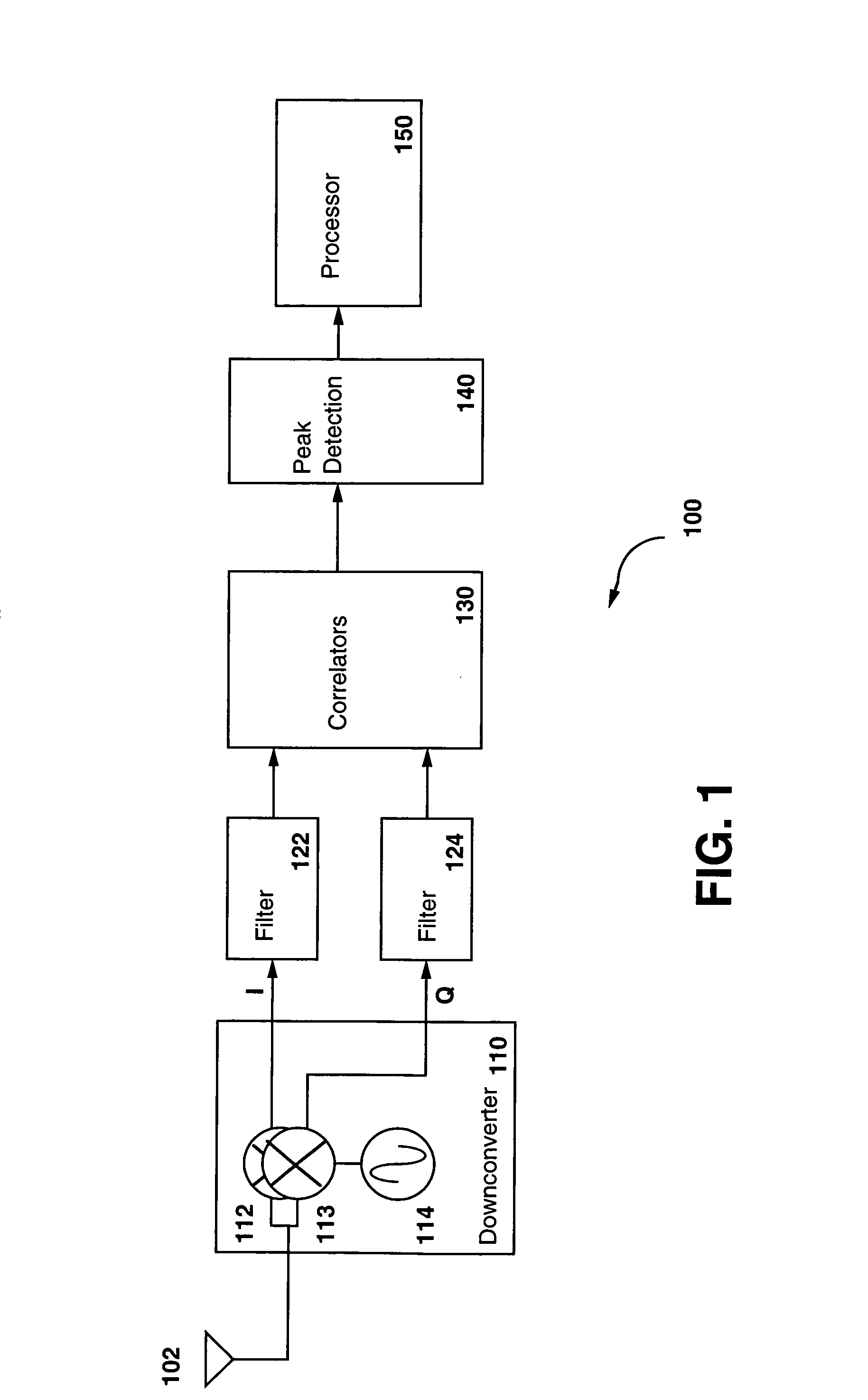
[0030]FIG. 1 is a block diagram of a generic receiver 100. The antenna 102 serves as the interface between broadcast signals and the receiver 100. The antenna 102 is tuned to optimally receive signals transmitted in the L-Band where the receiver 100 is configured as a GPS receiver. In the case of a GPS receiver, the source of the broadcast signals is the constellation of GPS satellites orbiting the earth. The signals received by the antenna 102 are coupled to a downconverter 110. The downconverter 110 serves to downconvert the RF signals received by the antenna 102 to baseband signals that are further processed. The main components of the downconverter 110 are the mixers 112 and the Local Oscillator (LO) 114. The downconverter 110 may also include filters and amplifiers (not shown) to maximize the quality of the resultant baseband signal. The received signal is coupled from the antenna 102 to the mixer 112 within the downconverter 110. Any filtering or amplification of the signal wi...


PUM


Abstract

The frequency error of an oscillator is minimized by characterizing the oscillator. A reference signal from an external source containing a minimal frequency error is provided to an electronic device. The external signal is used as a reference frequency to estimate the frequency error of an internal frequency source. The electronic device monitors parameters that are determined to have an effect on the frequency accuracy of the internal frequency source. Temperature is one parameter known to have an effect on the frequency of the internal frequency source. The electronic device collects and stores the values of the parameters as well as the corresponding output frequency or frequency error of the internal frequency source. The resultant characterization of the internal frequency source is used to compensate the internal frequency source when the internal frequency source is not provided the external reference signal.

Description

BACKGROUND OF THE INVENTION[0001]I. Field of the Invention[0002]The present invention relates to electronic circuits. More particularly, the present invention relates to a novel and improved method and apparatus for compensating Local Oscillator (LO) frequency error by characterizing the LO frequency over time.[0003]II. Description of the Related Art[0004]Accurate frequency sources are vital to the operation of numerous electronic systems and devices. Frequency sources are used as timing sources within electronic devices and are also used as Local Oscillators (LO) to tune electronic devices to desired communication channels.[0005]Many types of accurate frequency sources are available. The specific type of frequency source implemented within a particular application is determined according to the design constraints of the particular application. Atomic clocks exhibit extreme levels of frequency accuracy, however, their size, cost, and absence of tuning range greatly limit their actua...

Claims


Application Information

Patent Timeline
IPC IPC(8): G01S1/00H03J7/02H03L7/18H03L1/00H03J7/04H03L7/16H03L1/02H04B1/707H04L27/00G01S7/40G01S19/03G01S19/23H03L7/06
CPCG01S19/235H03J7/04H03L1/00H03L7/18H03L1/026H04B1/707H04L2027/0016H03L7/00
Inventor PATRICK, CHRISTOPHERYOUNIS, SAED G.
Owner QUALCOMM INC
Why Eureka
Try Eureka