Apparatus for fine pulverization of dry leaves and garden debris

a technology for dry leaves and garden debris, applied in the field of leaf grinding apparatus, can solve problems such as initial pulverization, and achieve the effects of enhancing soil fertility, high reliability of operation, and being easy to constru

Inactive Publication Date: 2005-08-16
NWOSU MICHAEL U +1
View PDF23 Cites 8 Cited by
  • Summary
  • Abstract
  • Description
  • Claims
  • Application Information

AI Technical Summary

Benefits of technology

[0024]The present invention provides a lawn debris composter that is lightweight, mobile, inexpensive to construct and highly reliable in operation. When deployed over grassy areas contiguous residential and commercial buildings, the composter automatically draws leaves, sticks, grass and other garden refuse into a suction and grinding chamber, pulverizes it into small evenly sized particles, which are either i) collected in a side collection chamber attached to the suction and grinding chamber and discharged by opening a gate at a user selected location or ii) automatically distributed uniformly over the lawn. Soil fertility is enhanced by the addition of organic matter, and the amount of raked leaves and grasses accumulating in landfills is reduced. The suction or drawing of leaves into the suction and grinding chamber is accomplished by 1) the rotation of a distribution plate with special geometrical features; or 2) rotation of an fan impeller blades and the rotation of said distribution plate.
[0025]Generally stated, there is provided a composter for finely pulverizing lawn debris. The composter has a central drive shaft driven by a gasoline or electrical power source. Preferably, the composter draws the leaves and lawn debris into a suction and grinding chamber by a specially configured low cost distributing plate. Inside the suction and grinding chamber, the leaves are pulverized by the action of grinding blades and discharged onto the lawn surface through the same specially configured distributing plate, thereby enriching the organic matter content of the lawn. The composter may optionally be equipped with fan impeller blades mounted on the central drive shaft above the grinding blades. In this case suction is provided both by the distributing plate and the fan impeller blades. In this, optional configuration, the distributing plate may be stopped by disengaging a clutch located in the central drive shaft. Pulverized debris is then diverted to a side collection chamber and may be discharged therefrom by the user at a suitable location by operating a sliding gate incorporated in the bottom of side collection chamber.
[0027]The second embodiment provides a composter having each of the features of the first embodiment; but additionally including a fan impeller blade mounted on the central drive shaft above the grinding blades. The rotation of the fan impeller blade provides additional suction power to draw the garden debris into the suction and grinding chamber. The fan impeller blades may have two to six fan blade elements and may preferably have four fan blade elements. Immediately below the fan impeller there are one or more grinding blades. The passage of the garden debris through the fan impeller blades results in initial pulverization. Fine pulverization of the lawn and garden debris is accomplished by the rotation of the grinding blades. Immediately below the grinding blades is a specially configured distributing plate which, as discussed above, provides drawing and distribution functions. The drawing function enables smooth flow of finely pulverized debris from the suction and grinding chamber to the lawn as a high-speed distribution stream.
[0029]In a fourth embodiment, the composter has all the features of the third embodiment and, in addition, includes a slidable isolation gate disposed between the suction and grinding chamber and the side collection chamber. The slidable isolation gate is opened by pulling on a sheathed cable attached to a user-controlled lever. This isolation gate is opened simultaneously with the disengagement of the clutch that stops the rotation of the distributing plate. When the distributing plate is rotating the finely pulverized lawn debris is directed to the lawn without being directed to the side collection chamber since the slidable isolation gate is closed. Opening a bottom discharge gate located at the bottom of the side collection chamber discharges the collected finely pulverized debris at a convenient user selected location. This feature is particularly useful when leaves and other garden debris are collected over a black top pavement, where the distribution of pulverized debris does not provide enrichment of soil fertility and the collected pulverized debris may be suitably applied to the soil at a desired location in the garden.

Problems solved by technology

The passage of the garden debris through the fan impeller blades results in initial pulverization.

Method used


Image

  • Apparatus for fine pulverization of dry leaves and garden debris
  • Apparatus for fine pulverization of dry leaves and garden debris
  • Apparatus for fine pulverization of dry leaves and garden debris

Examples


first embodiment

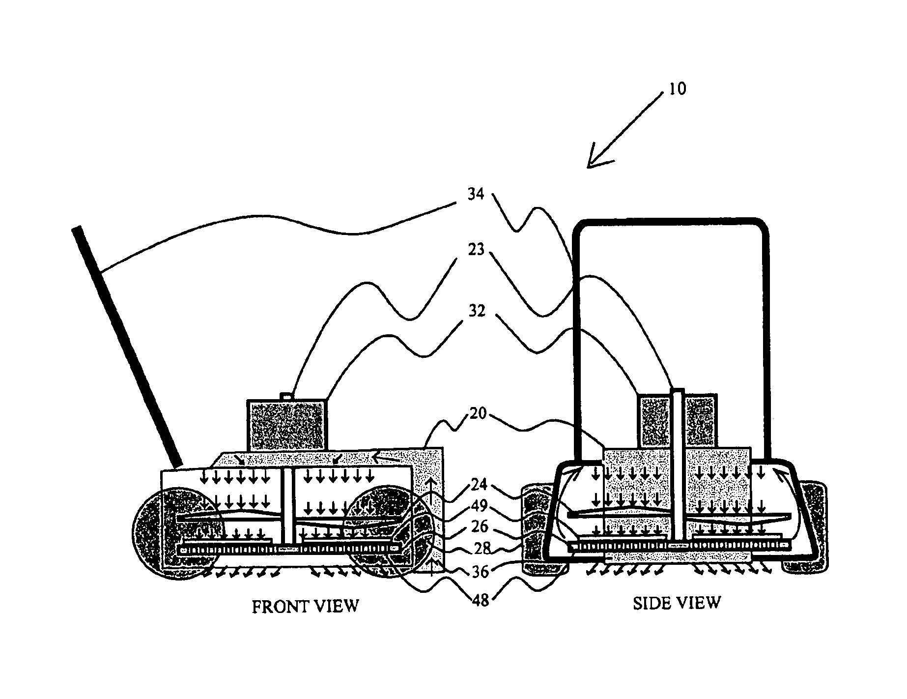
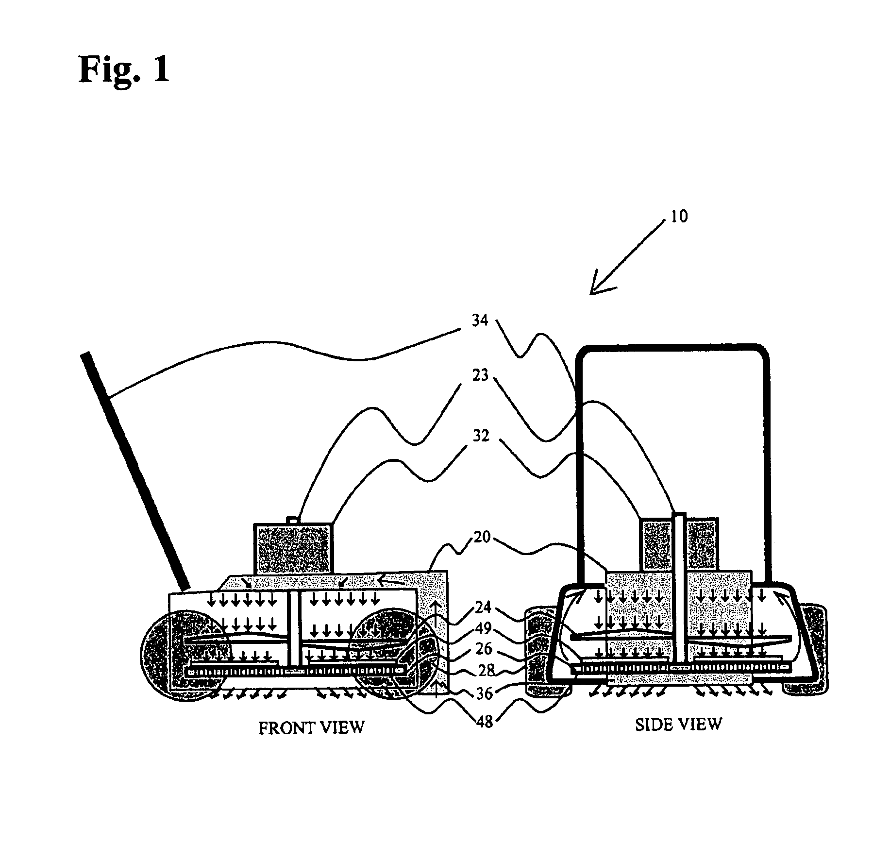
[0042]Referring to FIG. 1 of the drawings, the first embodiment is illustrated schematically, a composter 10 mounted on transportation wheels 28 and is pushed by handle 34 in the manner of a lawn mower, lime spreader or the like. The machine has a power source comprised of a gasoline engine or electrical motor 32 connected to drive shaft 23. The machine picks up leaves through a suction hood 36 located at the front of the device. Pick-up is accomplished by negative pressure generated from the rotation of the specially configured distributing plate 26, which has perforated plate 48 and curved impellers 49 attached to drive shaft 23. Lawn debris is drawn into this suction and grinding chamber with a nearly vertical flow pattern. The debris is pulverized by the grinding blades 24. The finely pulverized lawn and garden debris is uniformly distributed by the specially configured distributing plate 26, which has perforated plate 48 and curved impellers 49.

second embodiment

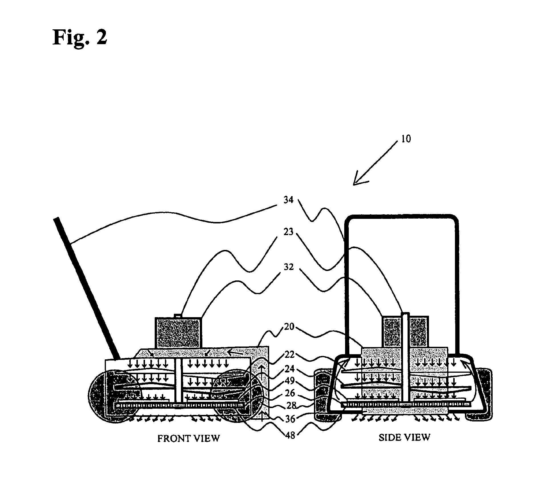
[0043]Referring to FIG. 2 of the drawings, the second embodiment is illustrated schematically, a composter 10 mounted on transportation wheels 28 and is pushed by handle 34 in the manner of a lawn mower, lime spreader or the like. The machine has a power source comprised of a gasoline engine or electrical motor 32 connected to drive shaft 23. The machine picks up leaves through a suction hood 36 located at the front of the device. Pick-up is accomplished by negative pressure generated from the rotation of fan impeller blades 22 and rotation of the specially configured distributing plate 26. In the embodiment shown, the fan impeller comprises four blade elements attached to drive shaft 23. Upon rotation of the fan impeller blades 22, suction is created within the suction and grinding chamber 20 attached to suction hood 36. Lawn debris is drawn into this chamber with a nearly vertical flow pattern. The lawn debris enters the suction and grinding chamber 20, being entrained by the air ...

third embodiment

[0044]Referring to FIG. 3 of the drawings, the third embodiment is illustrated schematically, a composter 10 mounted on transportation wheels 28 and is pushed by handle 34 in the manner of a lawn mower, lime spreader or the like. The machine has a power source comprised of a gasoline engine or electrical motor 32 connected to a drive shaft 23. The machine picks up leaves through a suction hood 36 located at the front of the device. Pick-up is accomplished by negative pressure generated from the rotation of fan impeller blades 22. In the embodiment shown, the fan impeller comprises four blade elements attached to drive shaft 23. Upon rotation of the fan impeller blades 22, and the distributing plate 26, suction is created within the suction and grinding chamber 20 attached to the suction hood 36. Lawn debris is drawn into this chamber with a nearly vertical flow pattern. The lawn debris enters the suction and grinding chamber 20, being entrained by the air stream created by the fan i...


PUM


Abstract

An apparatus for finely pulverizing lawn debris has a central drive shaft driven by a gasoline or electrical power source. Lawn debris is drawn into a suction and grinding chamber by the rotation of a distribution plate which has a plurality of curved impeller blades permanently attached to a perforated plate. A grinding blade with a plurality of blade elements is mounted on the central drive shaft above the distribution plate and effects pulverization of the debris. The distributing plate apertures dispense the pulverized debris uniformly over a lawn. Optionally, additional fan impeller blades may be mounted on the central drive shaft to draw and initiate pulverization of the debris. In this case, the rotation of the distributing plate may be stopped by disengaging a clutch mounted on the central shaft to direct pulverized debris to a side collection chamber, which is periodically emptied through a bottom discharge gate.

Description

[0001]This is a Continuation-In-Part of application Ser. No. 10 / 794,984, filed Mar. 5, 2004 which, in turn, is a Continuation-In-Part of application Ser. No. 10 / 340,456, filed Jan. 10, 2003, now U.S. Pat. No. 6,701,698, the disclosures of which are hereby incorporated in their entirety by reference thereto.BACKGROUND OF THE INVENTION[0002]1. Field of the Invention[0003]The present invention relates to a leaf grinding apparatus; and more particularly, to a portable composter that automatically picks-up lawn debris, pulverizes it into a fine compostable powder, and either i) collects it in a side collection chamber so that it may be suitably discharged at a user selected location at a later time or ii) automatically distributes it uniformly over the lawn to enhance the appearance thereof and improve soil fertility.[0004]2. Description of the Prior Art[0005]Those responsible for maintenance of the grounds of homes and commercial buildings have long struggled to devise a method and mean...

Claims


Application Information

Patent Timeline
Patent Type & Authority Patents(United States)
IPC IPC(8): A01D34/00
CPCA01D34/005A01D2101/00Y10S56/05
Inventor NWOSU, MICHAEL U.NDUMELE, ERIC S.
Owner NWOSU MICHAEL U
Why Eureka
Try Eureka