Optical fiber producing method

a technology of optical fiber and production method, applied in the direction of lighting and heating apparatus, instruments, furniture, etc., can solve the problem of fluctuation of optical fiber diameter

Inactive Publication Date: 2005-08-16
SUMITOMO ELECTRIC IND LTD
View PDF24 Cites 17 Cited by
  • Summary
  • Abstract
  • Description
  • Claims
  • Application Information

AI Technical Summary

Benefits of technology

[0019]When the predetermined gas is introduced inside the barrier by way of the gas inlet formed in the barrier, the He gas is actively let out from the gas outlet, whereby the dust occurring within the drawing furnace can further be restrained from entering the protecting tube.

Problems solved by technology

As a consequence, turbulence occurs in the gas flow in the space near the neck-down part, whereby the optical fiber diameter fluctuates greatly.

Method used


Image

  • Optical fiber producing method
  • Optical fiber producing method
  • Optical fiber producing method

Examples


first embodiment

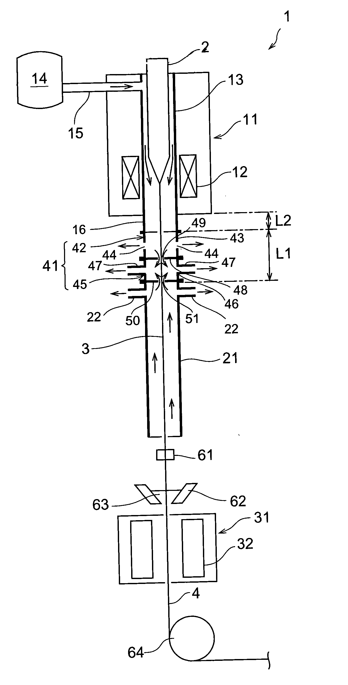
[0028]To begin with, a first embodiment of the method of making an optical fiber in accordance with the present invention and the drawing apparatus used in this method will be explained with reference to FIG. 1.

[0029]This drawing apparatus 1 is a drawing apparatus for silica type optical fibers; and comprises a drawing furnace 11, a protecting tube 21, and a resin curing unit 31. The drawing furnace 11, protecting tube 21, and resin curing unit 31 are disposed in this order in the drawing direction of an optical fiber preform 2 (from the upper side to the lower side in FIG. 1). The optical fiber preform 2 held by a preform supply apparatus (not depicted) is supplied to the drawing furnace 11, the lower end of the optical fiber preform 2 is heated and softened by a heater 12 within the drawing furnace 11, and an optical fiber 3 is drawn. An He gas supply path 15 from an He gas supply unit 14 is connected to a muffle tube 13 of the drawing furnace 11, whereby the muffle tube 13 within...

second embodiment

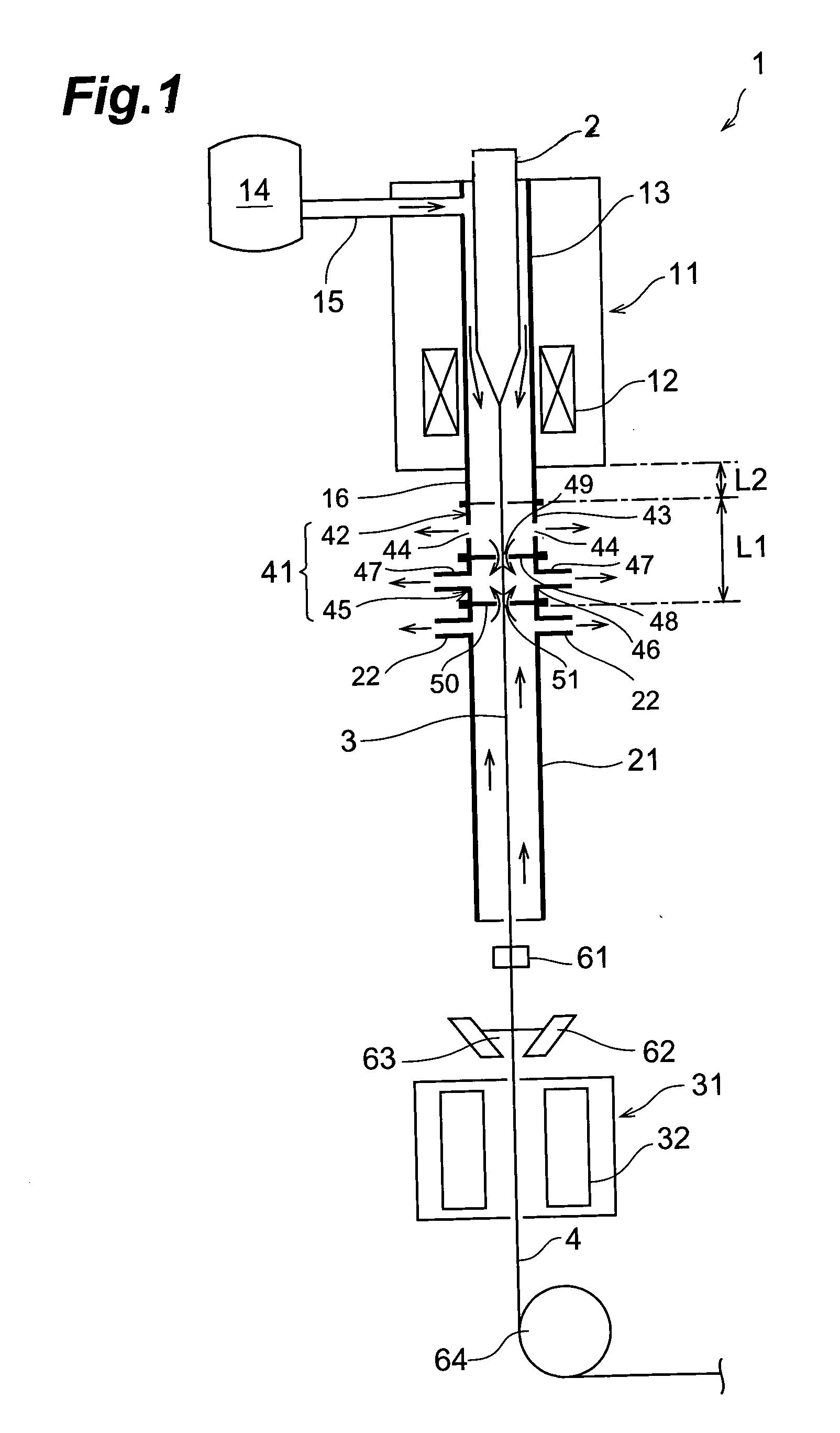
[0039]With reference to FIG. 2, a second embodiment of the method of making an optical fiber in accordance with the present invention and the drawing apparatus used for this method will now be explained. The second embodiment differs from the first embodiment in the structure of the buffer chamber.

[0040]In this drawing apparatus 101, a buffer chamber 141 is disposed between the muffle tube extension 16 and the protecting tube 21. The buffer chamber 141 has a length of L3 in the drawing direction of the optical fiber 3 as shown in FIG. 2. In the space within the buffer chamber 141, the He gas, which is an atmosphere gas within the drawing furnace 11 (the muffle tube 13), and the air, which is an atmosphere gas within the protecting tube 21, exist in a mixed state. It is not always necessary to provide the outlet ducts 22.

[0041]The buffer chamber 141 has a barrier 142 for separating the inner space, through which the optical fiber 3 passes, from the outside air. The barrier 142 is for...

third embodiment

[0042]With reference to FIG. 3, a third embodiment of the method of making an optical fiber in accordance with the present invention and the drawing apparatus used for this method will now be explained. The third embodiment differs from the first and second embodiments in the structure of the buffer chamber.

[0043]In this drawing apparatus 201, a buffer chamber 241 is disposed between the muffle tube extension 16 and the protecting tube 21. The buffer chamber 241 has a length of L4 in the drawing direction of the optical fiber 3 as shown in FIG. 3.

[0044]A slight gap (e.g., about 1 to 1.5 cm) exists between the muffle tube extension 16 and the buffer chamber 241, whereby the muffle tube extension 16 and the buffer chamber 241 are not directly connected to each other. It is not always necessary to provide a gap between the muffle tube extension 16 and the buffer chamber 241. They may also be configured so as to come into close contact with each other. It is sufficient for the gap betwe...


PUM

PropertyMeasurementUnit
temperatureaaaaaaaaaa
diameteraaaaaaaaaa
temperatureaaaaaaaaaa

Abstract

A drawing apparatus 1 comprises a drawing furnace 11, a protecting tube 21, and a resin curing unit 31. A buffer chamber 41 is disposed between the drawing furnace 11 and the protecting tube 21, and has a length L1 in the drawing direction of the optical fiber 3. The buffer chamber 41 is constituted by a first buffer cell 42 and a second buffer cell 45. In the space within the buffer chamber 41, an He gas, which is an atmosphere gas within the drawing furnace 11, and the air, which is an atmosphere gas within the protecting tube 21, exist in a mixed state. The optical fiber 3 drawn upon heating in the drawing furnace 11 is fed to the protecting tube 21, and a predetermined part of the optical fiber 3 is annealed at a predetermined cooling rate. Thereafter, a coating die 62 coats the optical fiber 3 with a UV resin solution 63, and the resin curing unit 31 cures the UV resin 63, whereby a coated optical fiber 4 is obtained.

Description

TECHNICAL FIELD[0001]The present invention relates to a method of making an optical fiber whose transmission loss is lowered by reducing its Rayleigh scattering intensity.BACKGROUND ART[0002]A drawing technique for drawing an optical fiber from an optical fiber preform having a large diameter (e.g., 70 mm) has been coming into common use due to demands for cutting down the cost of optical fiber, and the like. In the case where an optical fiber preform having a large thickness is to be drawn, the space surrounding its neck-down part becomes greater, whereby the gas flowing through this space exhibits an uneven temperature distribution. As a consequence, turbulence occurs in the gas flow in the space near the neck-down part, whereby the optical fiber diameter fluctuates greatly. For restraining the optical fiber diameter from fluctuating, there is a case where an He gas having a high thermal conductivity is used as the atmosphere gas within the drawing furnace.[0003]Also known is a te...

Claims


Application Information

Patent Timeline
Patent Type & Authority Patents(United States)
IPC IPC(8): C03B37/02C03B37/027C03B37/029G02B6/00
CPCC03B37/02718C03B37/029C03B2205/56C03B2205/82C03B2205/83C03B2205/90
Inventor NAGAYAMA, KATSUYAOHGA, YUICHIKUWAHARA, KAZUYATSUCHIYA, ICHIRO
Owner SUMITOMO ELECTRIC IND LTD
Why Eureka
Try Eureka