Apparatus for controlling a lubrication fluid level

a technology of lubrication fluid and apparatus, which is applied in the direction of lubricant level maintenance, lubrication elements, lubrication indication devices, etc., can solve the problems of lubricant quantity being too large, oil level in the sump not being the same, and oil being topped up, so as to reduce the quantity of lubricant pumped back to the container, prolong the change interval, and minimize the effect of lubricant quantity

Inactive Publication Date: 2005-08-16
VOLVO LASTVAGNAR AB
View PDF4 Cites 13 Cited by
  • Summary
  • Abstract
  • Description
  • Claims
  • Application Information

AI Technical Summary

Benefits of technology

[0026]An advantageous fifth development of the method according to the invention includes the step of detecting that topping up with a sufficient quantity of lubricant has taken place. The detection signal can be used to turn off the pump which transfers lubricant. The advantage of this is that the quantity of lubricant which is pumped back to the container can be minimized.
[0027]An advantageous sixth development of the method according to the invention includes the step of, if the control system has detected that topping up with a sufficient quantity of lubricant has not taken place, sending a message via the control system to an operator. The advantage of this is that the operator is made aware that topping up with a sufficient quantity of lubricant could not take place.
[0028]Conventionally, the oil sump in an engine with a wet sump contains a greater quantity of oil than is necessary to achieve safe lubrication. The reason for this is to allow longer topping-up intervals and longer change intervals. A sump of a heavy-duty vehicle can contain up to 50 liters of oil. A normal oil change interval for heavy-duty trucks may be, for example, 45000 km. The level between minimum and maximum may be, for example, 8 liters. This means that it may be necessary to top up the oil a few times a month. Apart from longer topping-up intervals and longer change intervals, there is no advantage in having a great volume of oil in the oil sump.
[0029]On the other hand, there are many advantages in keeping the total quantity of oil in the sump at as low a level as possible, without on this account jeopardizing the lubrication of the engine. It is furthermore advantageous if the difference between the maximum and minimum levels can be kept as small as possible. One advantage of this is that friction losses (splash losses) are reduced. There is thus less oil mist in the blow-by gases which leads to lower oil consumption. Another advantage is that, with a smaller quantity of oil but the same oil-cleaning system, that is to say oil pump and oil filter, the cleanness of the oil increases as the number of times the entire quantity of oil passes through the oil filter per unit of time increases exponentially with reduced oil volume. The quicker the oil is cleaned, the fewer particles there are in the oil. Above all, it is important that large particles are cleaned out rapidly; otherwise, such large particles are ground down into smaller particles which increases the total particle surface area and thus the degree of contamination of the oil. With a high degree of cleaning, the oil can be kept sufficiently clean that oil change intervals can be extended. One advantage of a smaller quantity of oil is that less oil has to be changed when the oil is changed. Another advantage of a small quantity of oil in the oil sump is that the oil sump can be made smaller, which saves weight. This also means that the engine can be made lower, which saves space.
[0030]With a system according to the invention, a normal service is limited to topping up the oil container. The size of this is selected so that it does not have to be topped up too often. With a volume of, for example, 20 liters, it is sufficient to top up the oil every other month, and perhaps even less often. The extra container can moreover be designed and positioned in such a manner that it is easy to inspect its oil level and easy to top it up with oil. The container can also be designed so that it is easily replaceable. The container can then comprise an apparatus which allows lubricant to come out of the container only when the container is placed in a special holder.
[0031]In an advantageous embodiment, the system is actuated after a predefined time passes after the engine has been turned off. The engine is drained of oil; that is to say, the quantity of oil with which the system operates is now located in the sump. As the oil is hot, and thus of low viscosity, the oil level in the sump will be horizontal and planar. This is especially important when oil is pumped back to the container in order to achieve a predefined oil level. If, on the other hand, the oil is very cold, and thus viscous, only oil in the vicinity of the mouth of the level pipe will be drawn off. A form of depression will then be created in the oil in the vicinity of the mouth of the level pipe, and it will take a long time for the oil level to become uniform throughout the oil sump. It is therefore advantageous that this system operates with a hot engine.

Problems solved by technology

One disadvantage is that oil is topped up only when the engine starts.
When it is cold and the oil is of high viscosity, the oil will flow out slowly, which results in the oil level in the sump not being the same everywhere during topping up.
This in turn leads to the quantity of oil in the sump being too great when the level sensor reacts.
Another disadvantage of this system is that it utilizes a sensor that stops the topping-up process.
A third disadvantage is that the system requires an oil level sensor mounted in the sump, where it is exposed to vibrations, temperature cycles, old oil, and other detrimental conditions.
A further disadvantage is that the oil in the external container is mixed with oil from the sump.
If the oil level is still too low, an error signal is generated and the ignition switch is locked.
Above all, it is complicated and contains many components; for example, electrical components, that can give rise to reliability problems, which can lead to operation being disrupted.
As the oil level is measured in the measuring container, which is located outside the sump, even a slight inclination of the vehicle can result in the sump containing more oil than necessary, which can lead to increased friction losses (splash losses), more oil mist in the blow-by gases and thus higher oil consumption.
If this pipe is damaged, the engine is emptied of oil.
Moreover, this solution is costly.

Method used


Image

  • Apparatus for controlling a lubrication fluid level
  • Apparatus for controlling a lubrication fluid level
  • Apparatus for controlling a lubrication fluid level

Examples


Embodiment Construction

[0037]The illustrative embodiments of the invention with developments described below are to be regarded only as examples and are not in any way to limit the scope of protection of the patent claims. In this context, the lubricant is a mineral or synthetic engine oil, but could also be another substance with similar properties.

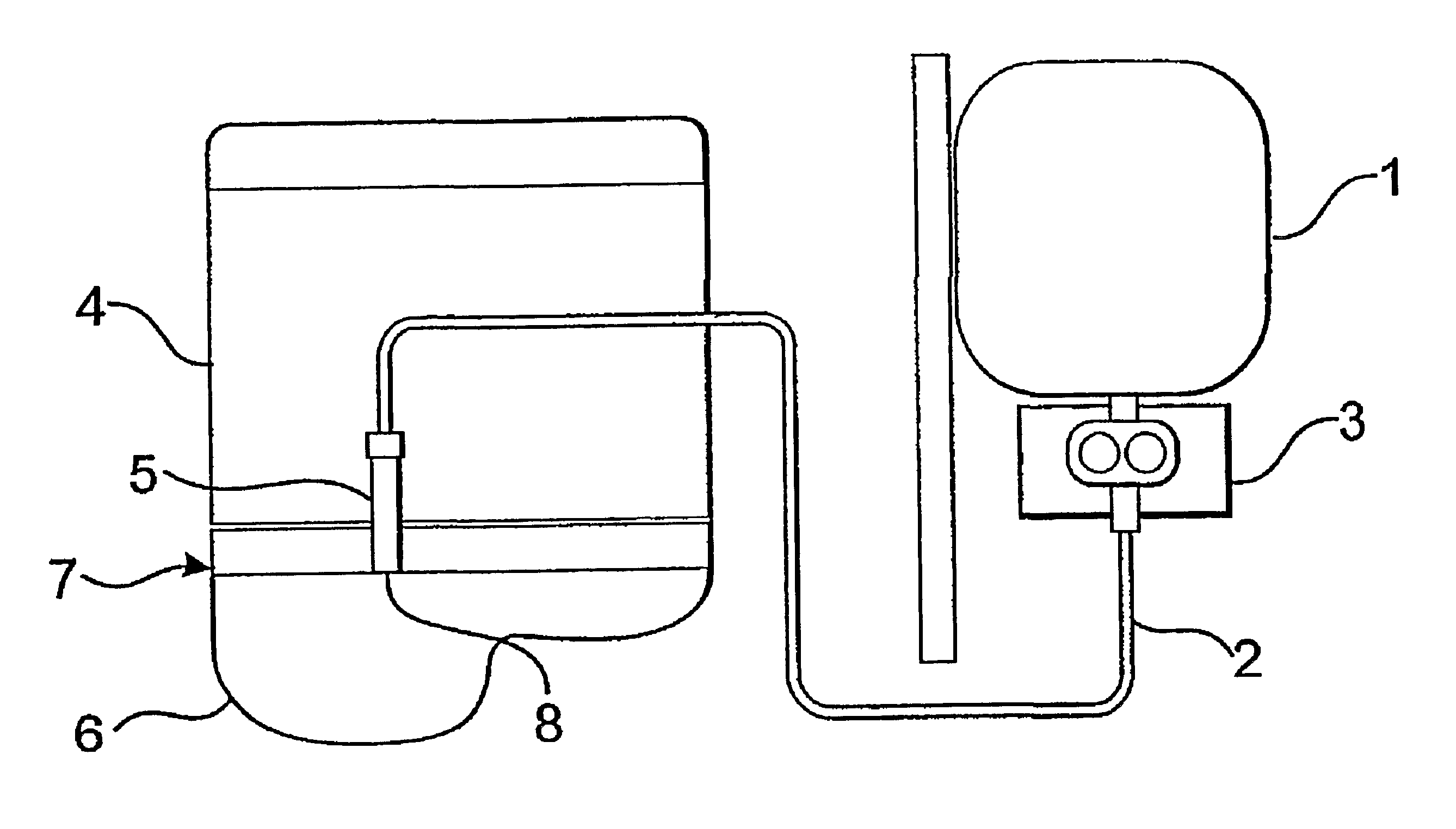
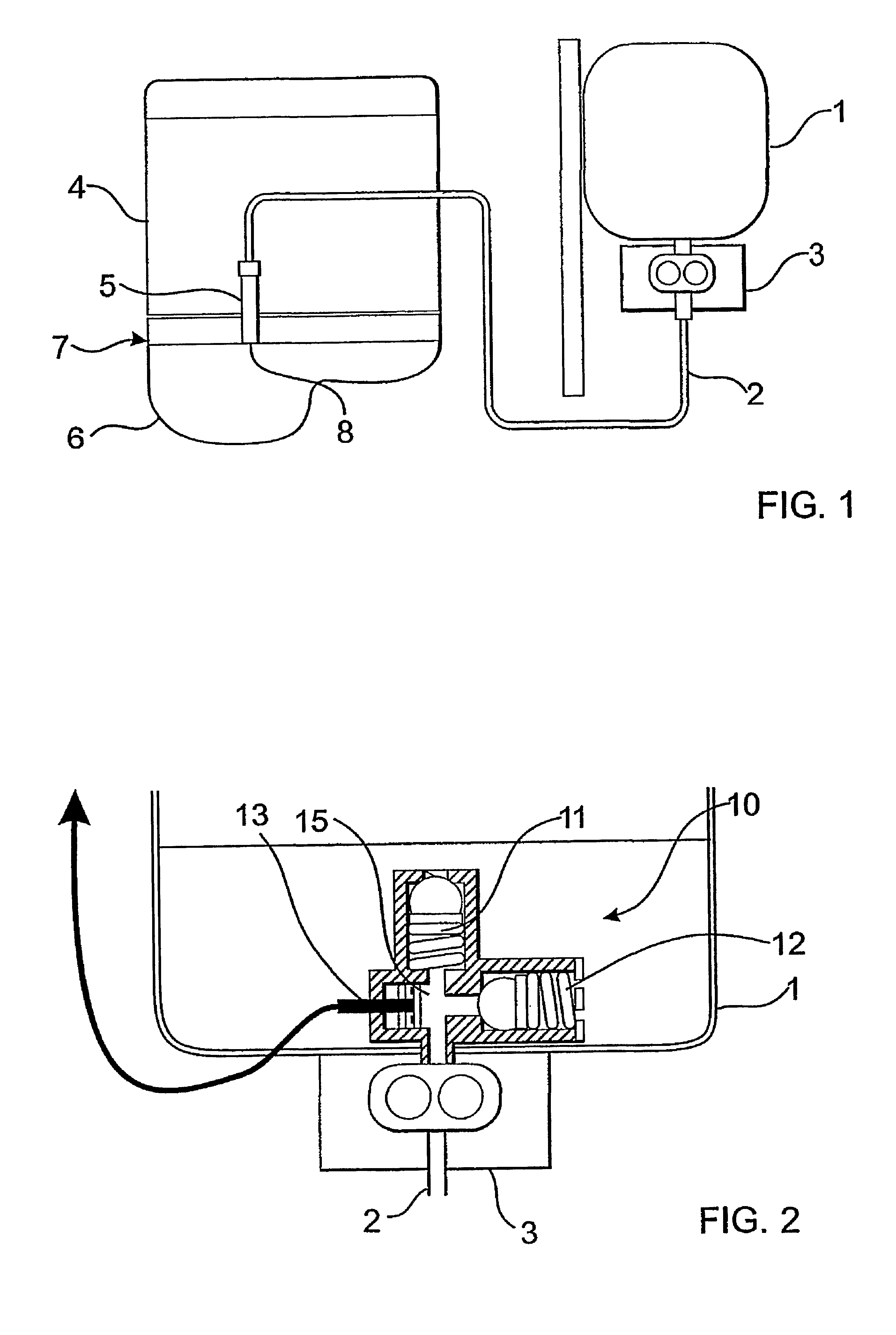
[0038]The first illustrative embodiment of a system for automatic topping up with oil shown in FIG. 1 consists of a container 1 for oil, a pipe 2 which connects the container 1 to the internal combustion engine 4, and an apparatus 3 for transferring oil. On the engine side, the pipe 2 is connected to a level pipe 5 which is positioned so that its mouth 8 is located in the oil sump 6. The height of the mouth 8 of the level pipe defines the optimum oil level limit 7 in the oil sump 6 for the engine. In order for it to be possible to reliably and accurately define an oil level with a level pipe 5 according to the invention, the mouth 8 of the level pipe is positi...


PUM


Abstract

System and a method for automatically topping up an internal combustion engine (4) with lubricant. A lubricant container that includes a (1), a pipe (2) which connects the container to the internal combustion engine (4), a level pipe (5) which defines the oil level in a sump (6) and an apparatus (3) for transferring lubricant. The apparatus (3) for transferring lubricant makes it possible to transfer lubricant both from the container (1) to the internal combustion engine (4) and from the internal combustion engine (4) to the container (1).

Description

CROSS REFERENCE TO RELATED APPLICATIONS[0001]This application is a continuation patent application of International Application No. PCT / SE02 / 00057 filed 14 Jan. 2002 which was published in English pursuant to Article 21(2) of the Patent Cooperation Treaty, and which claims priority to Swedish Application No. 0100151-0 filed 19 Jan. 2001. Both applications are expressly incorporated herein by reference in their entireties.BACKGROUND OF INVENTION[0002]1. Technical Field[0003]The present invention relates to a system and method for automatically topping up an internal combustion engine with lubricant.[0004]2. Background Art[0005]Various systems for automatically topping up the sump of an internal combustion engine with oil are well known.[0006]Such a system is described in EP 0638708 B1. When the engine is started, in the system described, oil is drawn into the sump from an external oil container by means of negative pressure. When a maximum permitted oil level is reached, an oil level...

Claims


Application Information

Patent Timeline
Patent Type & Authority Patents(United States)
IPC IPC(8): F01M11/04F01M11/00F01M11/06
CPCF01M11/04F01M11/06F01M2011/0466
Inventor H.ANG.KANSSON, NILS-OLOF
Owner VOLVO LASTVAGNAR AB
Why Eureka
Try Eureka