
Inkjet printhead chip for use with a pulsating pressure ink supply

Inactive Publication Date: 2005-08-16
SILVERBROOK RES PTY LTD +1
View PDF83 Cites 19 Cited by
  • Summary
  • Abstract
  • Description
  • Claims
  • Application Information

AI Technical Summary

Benefits of technology

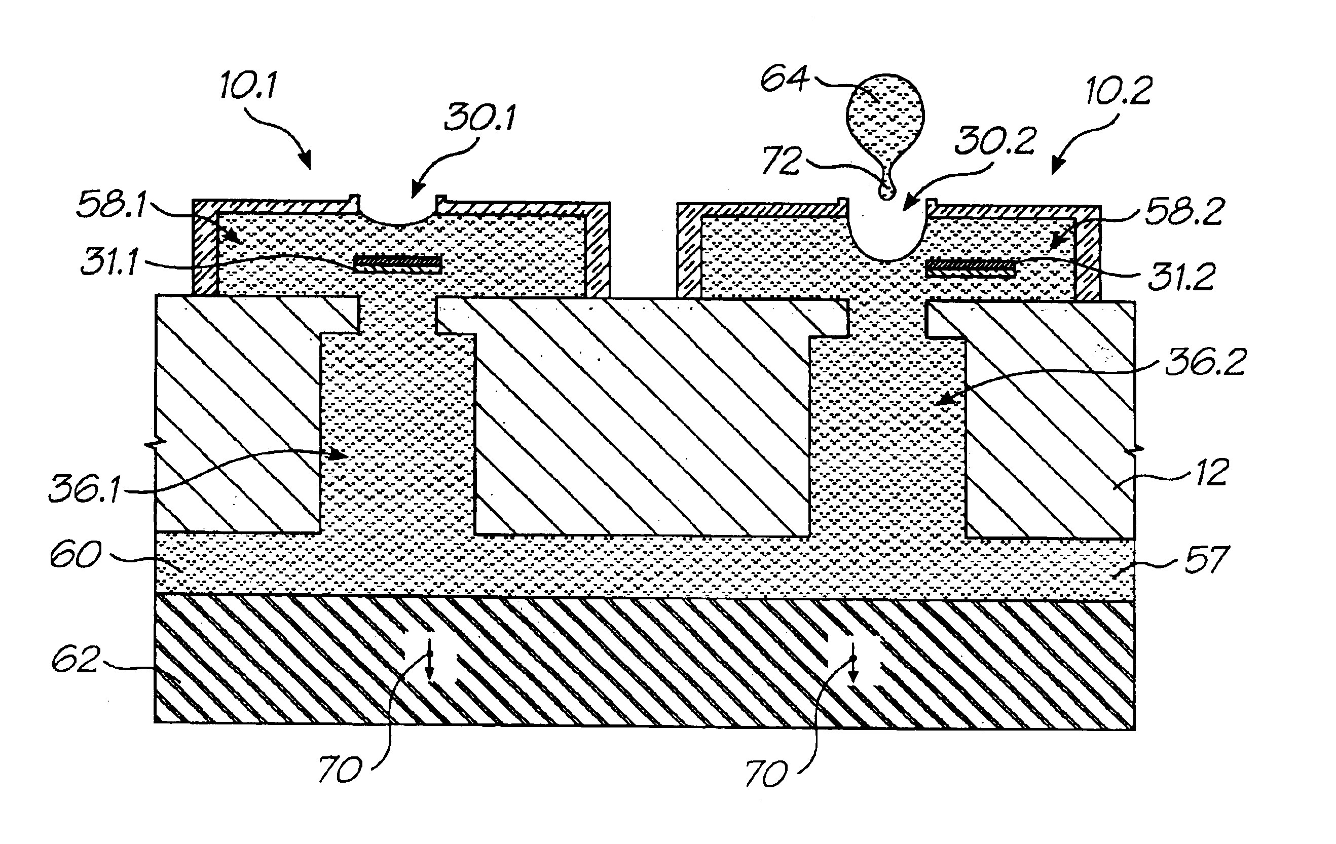
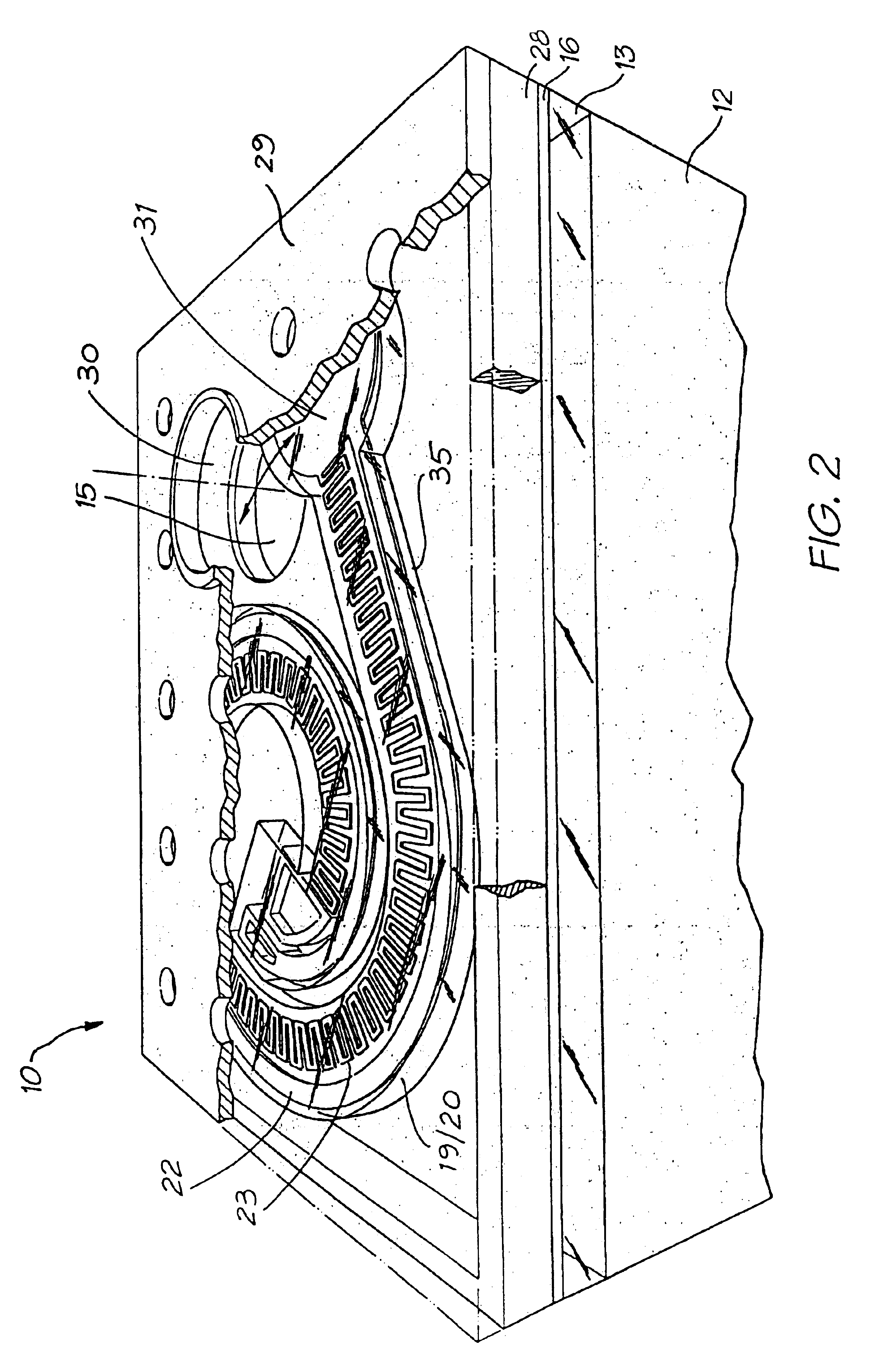
[0039]Further, the actuator preferably comprises a thermal actuator which is activated by the heating of one side of the actuator. Preferably the actuator has a coiled form and is uncoiled upon heating. The actuator includes a serpentine heater element encased in a material having a high coefficient of thermal expansion. The serpentine heater concertinas upon heating. Advantageously, the actuator includes a thick return trace for the serpentine heater element. The material in which the serpentine heater element is encased comprises polytetrafluoroethylene. The actuator is formed within a nozzle chamber which is formed on a silicon wafer and ink is supplied to the ejection port through channels etched through the silicon wafer.

Problems solved by technology

Each type of printer has its own advantages and problems when considering cost speed, quality, reliability, simplicity of construction and operation etc.
Each technology may have its own advantages and disadvantages in the areas of cost, speed, quality, reliability, power usage, simplicity of construction operation, durability and consumables.

Method used


Image

  • Inkjet printhead chip for use with a pulsating pressure ink supply
  • Inkjet printhead chip for use with a pulsating pressure ink supply
  • Inkjet printhead chip for use with a pulsating pressure ink supply

Examples


Embodiment Construction

[0049]In the preferred embodiment, an oscillating ink reservoir pressure is used to eject ink from ejection nozzles. Each nozzle has an associated shutter which normally blocks the nozzle. The, shutter is moved away from the nozzle by an actuator whenever an ink drop is to be fired.

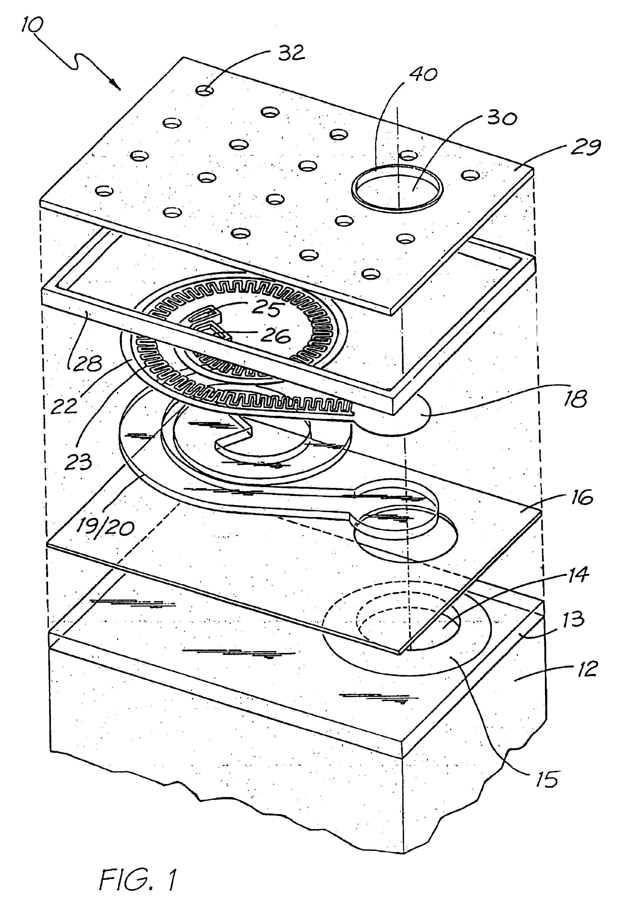
[0050]Turning initially to FIG. 1, there is illustrated in exploded perspective a single ink jet nozzle 10 as constructed in accordance with the principles of the present invention. The exploded perspective illustrates a single ink jet nozzle 10. Ideally, the nozzles are formed as an array on a silicon wafer 12. The silicon wafer 12 is processed so as to have two level metal CMOS circuitry which includes metal layers and glass layers 13 and which are planarised after construction. The CMOS metal layer has a reduced aperture 14 for the access of ink from the back of silicon wafer 12 via an ink supply channel 15.

[0051]A bottom nitride layer 16 is constructed on top of the CMOS layer 13 so as to cover, prote...


PUM


Abstract

An ink jet printhead chip includes a substrate that incorporates drive circuitry. A plurality of nozzle arrangements is positioned on the substrate. Each nozzle arrangement includes nozzle chamber walls that define a nozzle chamber and an ink ejection port in fluid communication with the nozzle chamber. The nozzle chamber is in fluid communication with an ink supply channel through the substrate for supplying the nozzle chamber with ink. A closure is operatively positioned with respect to the ink supply channel. The closure is displaceable between a closed position in which the closure closes the ink supply channel and an open position in which ink is permitted to flow into the nozzle chamber. An actuator is connected to the drive circuitry and the closure so that, on receipt of an electrical signal from the drive circuitry, the actuator can act to displace the closure between the closed and open positions. An ink reservoir is in fluid communication with each ink supply channel. A source of oscillating pressure imparts an oscillating pressure to ink in the reservoir, so that, when the closure is displaced into the open position, a drop of ink can be ejected from the ink ejection port.

Description

CROSS REFERENCES TO RELATED APPLICATIONS[0001]This is a Continuation Application of U.S. Ser. No. 10 / 302,606 filed on Nov. 23, 2002, now issued U.S. Pat. No. 6,644,767, which is a Continuation of Ser. No. 09 / 855,094 filed May 14, 2001, now issued U.S. Pat. No. 6,485,123 which is a Continuation-in-part of Ser. No. 09 / 112,815 filed on Jul. 10, 1998, now issued U.S. Pat. No. 6,247,792, the entire contents of which are herein incorporated by reference.[0002]The following Australian provisional patent applications are hereby incorporated by reference. For the purposes of location and identification. US patents / patent applications identified by their US patent / patent application serial numbers are listed alongside the Australian applications from which the US patents / patent applications claim the right of priority.[0003]US PATENT / PATENTCROSS-REFERENCEDAPPLICATION (CLAIMINGAUSTRALIAN PRO-RIGHT OF PRIORITYVISIONAL PATENTFROM AUSTRALIAN PRO-DOCKETAPPLICATION NO.VISIONAL APPLICATION)NO.PO7991...

Claims


Application Information

Patent Timeline
Patent Type & Authority Patents(United States)
IPC IPC(8): B41J15/04B41J2/045B41J2/14B41J11/70B42D15/10B41J2/175B41J2/16B41J3/42G06F1/16G06K1/00G06K1/12G11C11/56G07F7/12G07F7/08G06K19/06G06K7/14H04N1/21H04N5/225H04N5/262B41J2/165H04N1/00B41J2/04B41J3/44B41J11/00G06F21/00G06K19/073H04N1/32H04N5/74
CPCB41J2/14427B41J2/1623B41J2/1626B41J2/1628B41J2/1629B41J2/1631B41J2/1632B41J2/1635B41J2/1637B41J2/1639B41J2/1642B41J2/1643B41J2/1645B41J2/1646B41J2/1648B41J2/175B41J2/17503B41J2/17513B41J2/17596B41J3/445B41J11/0005B41J11/70B41J15/04G06F21/79G06F21/86G06K1/121G06K7/14G06K7/1417G06K19/06037G11C11/56H04N1/2112H04N1/2154H04N5/225H04N5/2628B41J2/16585B41J2002/041B41J2202/21B82Y30/00G06F2221/2129H04N5/7458H04N2101/00Y10S977/932H04N23/00
Inventor SILVERBROOK, KIA
Owner SILVERBROOK RES PTY LTD
Learn More