Ink-jet recording head, manufacturing method of the same, and ink-jet recording apparatus

a technology of ink-jet recording and manufacturing method, which is applied in the direction of printing, etc., can solve the problems of uneven film thickness of the vibrating plate, and the inability to stabilize the ejection characteristic of the ink to be ejected from the respective nozzle orifice, so as to eliminate the restriction of a region

Inactive Publication Date: 2005-08-16
SEIKO EPSON CORP
View PDF6 Cites 10 Cited by
  • Summary
  • Abstract
  • Description
  • Claims
  • Application Information

AI Technical Summary

Benefits of technology

[0039]In the fourteenth aspect, it is possible to eliminate restriction on a region for forming the etching adjustment layer within a region opposed to the piezoelectric element.

Problems solved by technology

Accordingly, there is a problem that film-thicknesses of the vibrating plates become uneven due to errors in etching rates in the thickness direction of the piezoelectric elements.
Accordingly there is a problem that ejection characteristic of the ink to be ejected from respective nozzle orifices is not stabilized.

Method used


Image

  • Ink-jet recording head, manufacturing method of the same, and ink-jet recording apparatus
  • Ink-jet recording head, manufacturing method of the same, and ink-jet recording apparatus
  • Ink-jet recording head, manufacturing method of the same, and ink-jet recording apparatus

Examples


embodiment 1

(Embodiment 1)

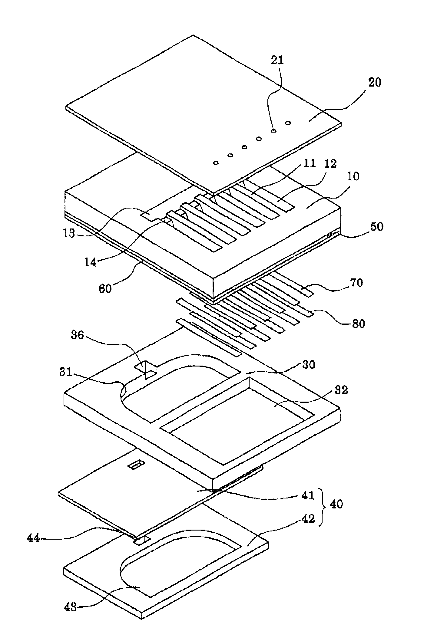
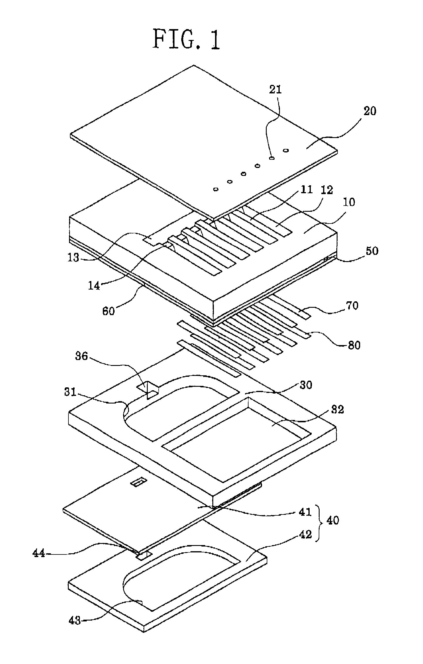
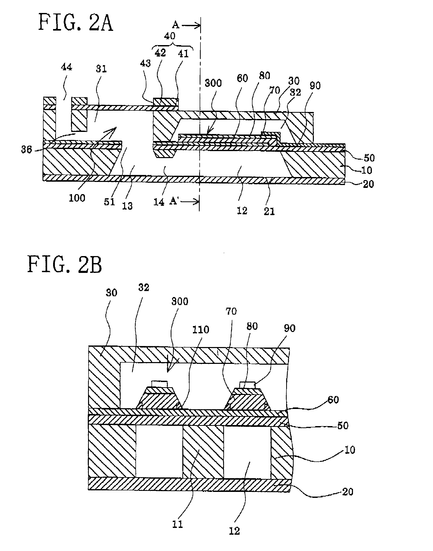
[0050]FIG. 1 is an exploded perspective view of an ink-jet recording head according to Embodiment 1 of the present invention. FIGS. 2A and 2B are a cross-sectional view of the ink-jet recording head along the longitudinal direction of a pressure generating chamber and a cross-sectional view taken along the A-A′ line thereof.

[0051]As illustrated therein, a passage-forming substrate 10 is made of a silicon single crystal substrate having a plane orientation (110) in this embodiment. On one surface thereof, there is formed an elastic film 50 in a thickness of 1 to 2 μm, which is made of silicon dioxide being formed in advance by thermal oxidation.

[0052]On this passage-forming substrate 10, pressure generating chambers 12 defined by a plurality of compartment walls are formed by anisotropic etching from the other surface side thereof. Moreover, on the outside of the pressure generating chambers 12 of each row in the longitudinal direction, there is formed a communicating p...

embodiment 2

(Embodiment 2)

[0092]FIGS. 6A and 6B are a cross-sectional view of an ink-jet recording head according to Embodiment 2 along the longitudinal direction of a pressure generating chamber and a cross-sectional view taken along the B-B′ line thereof.

[0093]As shown in FIG. 6, the ink-jet recording head of Embodiment 2 is similar to the above-described Embodiment 1, except that an etching adjustment layer 110A is formed on an entire surface between the lower electrode film 60 and the piezoelectric layer 70 of the piezoelectric element 300 being opposed by the piezoelectric element 300.

[0094]In such an etching adjustment layer 110A, in order to enable the piezoelectric layer 70 to be displaced by applying voltage between the lower electrode film 60 and the upper electrode film 80 of the piezoelectric element 300, the etching adjustment layer 110A needs to be formed of a conductive material such as a metallic material.

[0095]Note that it is preferable to set the thickness of the etching adjus...


PUM


Abstract

An ink-jet recording head is provided which possesses a stable ink ejection characteristic obtained by controlling a film thickness of a vibrating plate easily and reliably, a method of manufacturing the same, and an ink-jet recording apparatus. The ink-jet recording head having a passage-forming substrate on which pressure generating chambers communicating with nozzle orifices are defined, and a piezoelectric element composed of a lower electrode, a piezoelectric layer, and an upper electrode, which are provided on the passage-forming substrate while interposing a vibrating plate therebetween. Etching adjustment layers each having etching selectivity with the lower electrode film and the piezoelectric layer, are provided at least between the piezoelectric layer and the lower electrode as well as the vibrating plate in the vicinity of both end portions in the width direction of the piezoelectric element.

Description

BACKGROUND OF THE INVENTION[0001]1. Field of the Invention[0002]The present invention relates to an ink-jet recording head, in which part of a pressure generating chamber communicating with a nozzle orifice for ejecting ink droplets is composed of a vibrating plate and a piezoelectric element is formed on a surface of this vibrating plate so as to cause ejection of ink droplets by displacement of the piezoelectric element, a method of manufacturing the same, and an ink-jet recording apparatus.[0003]2. Description of the Related Art[0004]An ink-jet recording head, in which part of a pressure generating chamber communicating with a nozzle orifice for discharging ink droplets is composed of a vibrating plate, and which causes discharge of ink droplets out of the nozzle orifice by displacing this vibrating plate with a piezoelectric element and thereby pressurizing the ink in the pressure generating chamber, has two types that are already in practical use, namely, one using a piezoelect...

Claims


Application Information

Patent Timeline
Patent Type & Authority Patents(United States)
IPC IPC(8): B41J2/14B41J2/16B41J2/055B41J2/045
CPCB41J2/14233B41J2/161B41J2/1623B41J2/1628B41J2/1629B41J2/1631B41J2/1632B41J2/1646B41J2002/14241B41J2002/14419
Inventor MATSUZAWA, AKIRA
Owner SEIKO EPSON CORP
Why Eureka
Try Eureka