Cooled rotor blade with vibration damping device

a technology of vibration damping and rotor blade, which is applied in the direction of rotors, vessel construction, other chemical processes, etc., can solve the problems of thermal degradation of dampers, and achieve the effect of uniform dispersion of cooling air, facilitating the insertion of dampers, and avoiding undesirable cooling airflow impediments

Active Publication Date: 2005-08-16
RTX CORP
View PDF4 Cites 35 Cited by
  • Summary
  • Abstract
  • Description
  • Claims
  • Application Information

AI Technical Summary

Benefits of technology

[0013]An advantage of the present invention is that a more uniform dispersion of cooling air is enabled upstream of the damper, between the damper and the airfoil walls, and aft of the damper than is possible with the prior art of which we are aware. The more uniform dispersion of cooling air decreases the chance that thermal degradation will occur in the damper or the area of the airfoil proximate the damper.
[0014]Another advantage of the present invention is that a channel for receiving a damper that facilitates insertion of the damper within the airfoil, without creating undesirable cooling airflow impediments. Walls used as guide surfaces adjacent the channel either prevent the floe of cooling air or inhibit its distribution. In either case, the ability to cool the rotor blade is negatively effected. The present invention first and second pedestals; in contrast, promote uniform cooling air distribution.

Problems solved by technology

The more uniform dispersion of cooling air decreases the chance that thermal degradation will occur in the damper or the area of the airfoil proximate the damper.

Method used


Image

  • Cooled rotor blade with vibration damping device
  • Cooled rotor blade with vibration damping device
  • Cooled rotor blade with vibration damping device

Examples


Embodiment Construction

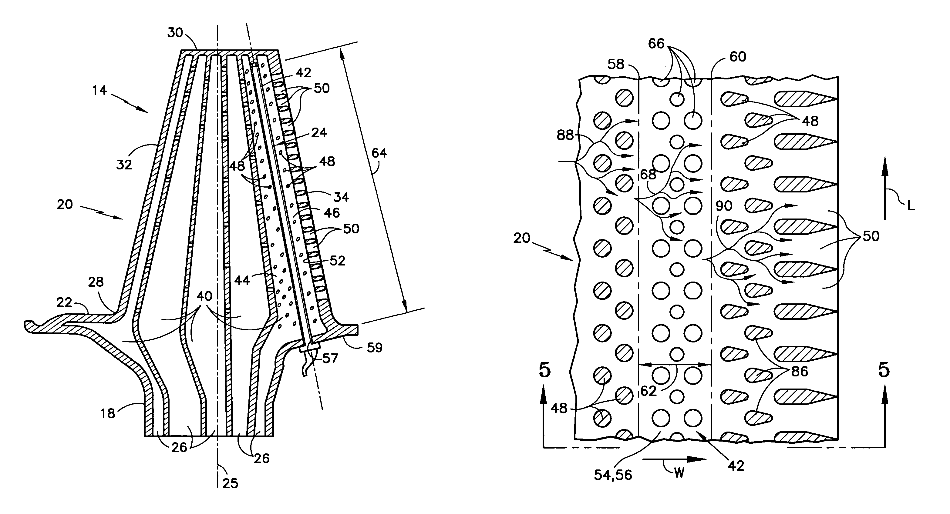
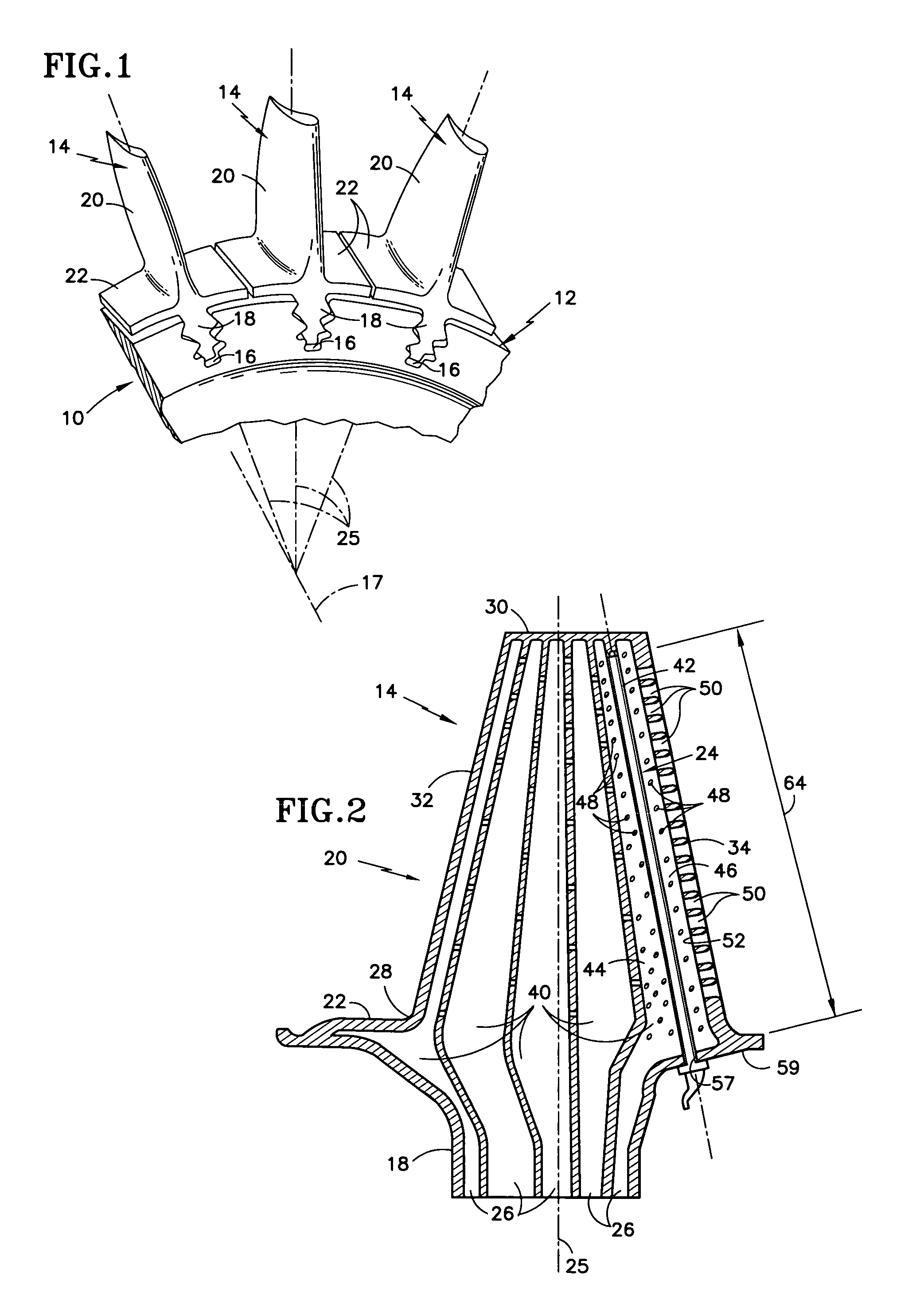
[0024]Referring to FIG. 1, a rotor blade assembly 10 for a gas turbine engine is provided having a disk 12 and a plurality of rotor blades 14. The disk 12 includes a plurality of recesses 16 circumferentially disposed around the disk 12 and a rotational centerline 17 about which the disk 12 may rotate. Each blade 14 includes a root 18, an airfoil 20, a platform 22, and a damper 24 (see FIG. 2). Each blade 14 also includes a radial centerline 25 passing through the blade 14, perpendicular to the rotational centerline 17 of the disk 12. The root 18 includes a geometry that mates with that of one of the recesses 16 within the disk 12. A fir tree configuration is commonly known and may be used in this instance. As can be seen in FIG. 2, the root 18 further includes conduits 26 through which cooling air may enter the root 18 and pass through into the airfoil 20.

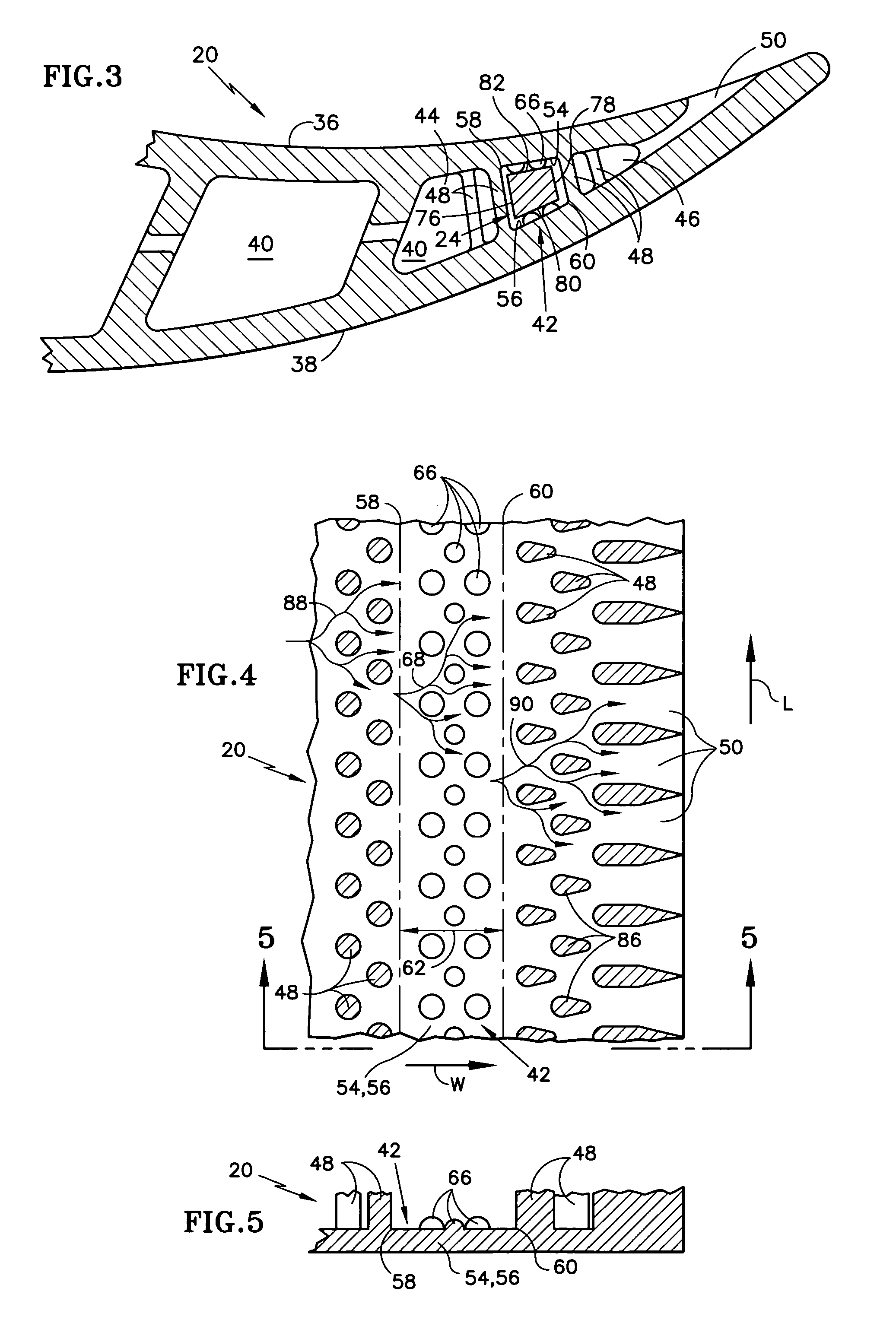
[0025]Referring to FIGS. 1–3, the airfoil 20 includes a base 28, a tip 30, a leading edge 32, a trailing edge 34, a pressure sid...


PUM


Abstract

A rotor blade for a rotor assembly is provided that includes a root, an airfoil, and a damper. The airfoil includes a base, a tip, a pressure side wall, a suction side wall, and a cavity disposed therebetween. The cavity extends substantially between the base and the tip, and includes a first cavity portion, a second cavity portion, and a channel disposed between the first cavity portion and the second cavity portion. A plurality of first pedestals are disposed within the first cavity portion adjacent the channel, and a plurality of second pedestals are disposed within the second cavity portion adjacent the channel. The damper is selectively received within the channel.

Description

[0001]The invention was made under a U.S. Government contract and the Government has rights herein.BACKGROUND OF THE INVENTION[0002]1. Technical Field[0003]This invention applies to rotor blades in general, and to apparatus for damping vibration within and cooling of a rotor blade in particular.[0004]2. Background Information[0005]Turbine and compressor sections within an axial flow turbine engine generally include a rotor assembly comprising a rotating disc and a plurality of rotor blades circumferentially disposed around the disk. Each rotor blade includes a root, an airfoil, and a platform positioned in the transition area between the root and the airfoil. The roots of the blades are received in complementary shaped recesses within the disk. The platforms of the blades extend laterally outward and collectively form a flow path for fluid passing through the rotor stage. The forward edge of each blade is generally referred to as the leading edge and the aft edge as the trailing edg...

Claims


Application Information

Patent Timeline
Patent Type & Authority Patents(United States)
IPC IPC(8): F01D5/16F01D5/14F01D5/18
CPCF01D5/16F01D5/187F01D5/189F01D5/26Y10S416/50F05D2240/126F05D2260/22141F05D2240/307
Inventor GREGG, SHAWN J.MONGILLO, JR., DOMINIC J.
Owner RTX CORP
Why Eureka
Try Eureka