Method of preventing repeated collapse in a reworked photoresist layer

Active Publication Date: 2005-08-16
NAN YA TECH
View PDF3 Cites 0 Cited by
  • Summary
  • Abstract
  • Description
  • Claims
  • Application Information

AI Technical Summary

Benefits of technology

[0007]Accordingly, an object of the present invention is to provide a method of preven

Problems solved by technology

In the process of making the desired very fine patterns, many optical effects are experienced which lead to distortion or displacement of images in the photoresist that are directly responsible for wiring line width variations, opens, and shorts, all of which c

Method used


Image

  • Method of preventing repeated collapse in a reworked photoresist layer
  • Method of preventing repeated collapse in a reworked photoresist layer
  • Method of preventing repeated collapse in a reworked photoresist layer

Examples


Example

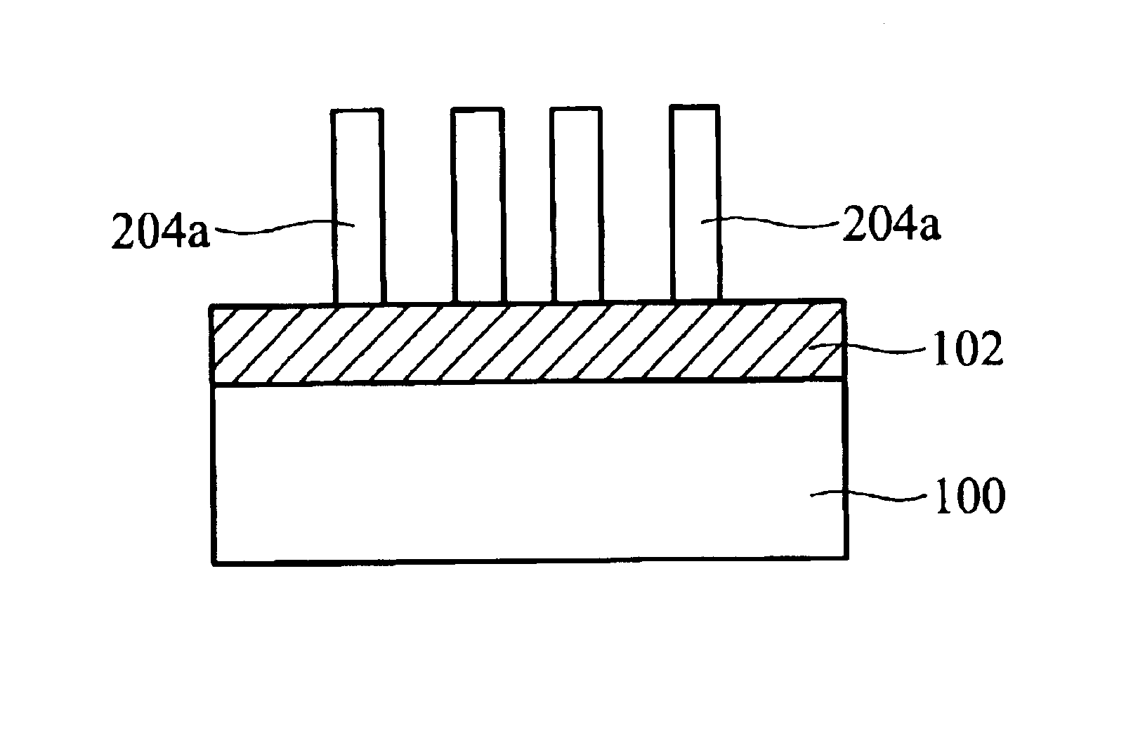
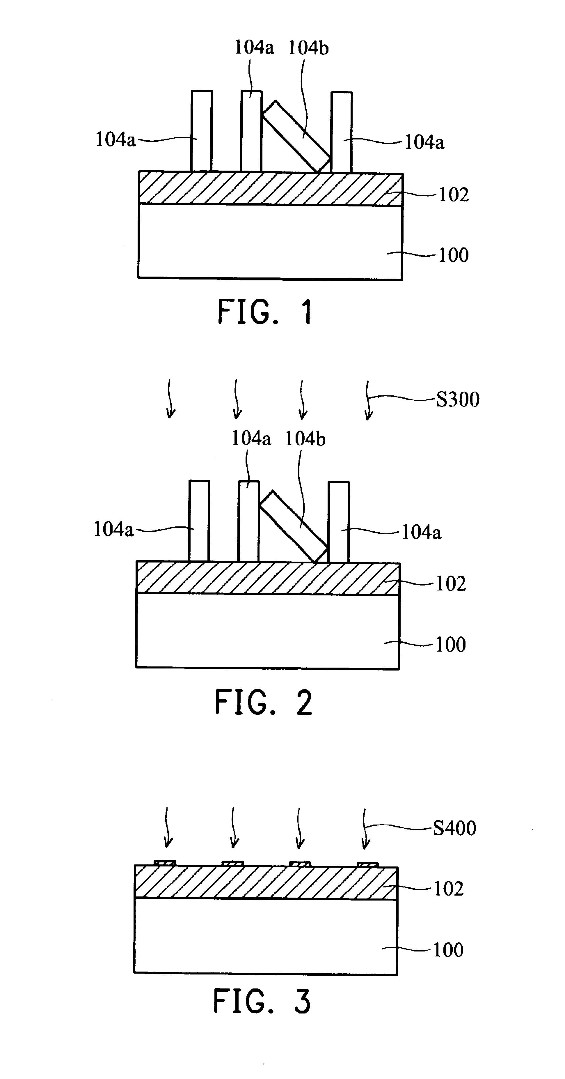
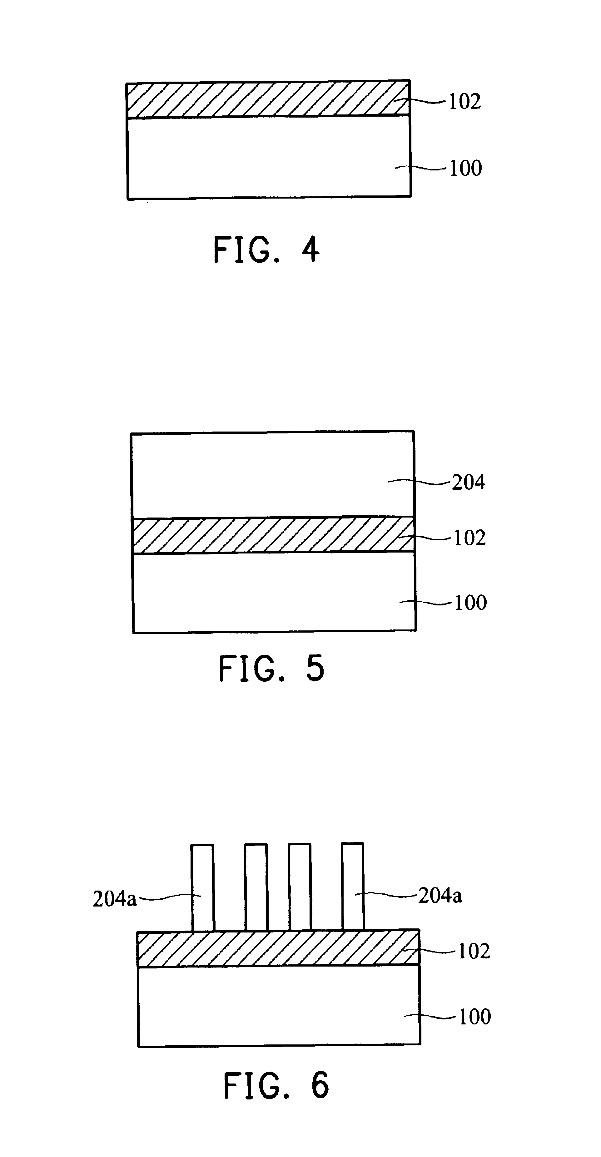
[0014]A preferred embodiment of the present invention is now described with reference to FIGS. 1 through 6.

[0015]First, as shown in FIG. 1, a substrate 100 with a defective photoresist layer 104a and 104b thereon, such as a collapsed photoresist 104b, is provided. As well, a bottom anti-reflect layer 102 comprising SiOxNy is interposed between the substrate 100 and the defective photoresist layer 104a and 104b to reduce reflection and enhance the resolution of the photoresist layer.

[0016]In FIG. 2, oxygen-containing plasma S300 is preferably applied to remove the collapsed photoresist layer 104a and 104b at about 280˜320° C. The oxygen flow is about 10˜20 slm, and the flow of carrier gas comprising nitrogen is about 100˜200 sccm. In the plasma process, the provided power is about 800˜1200 W, and the pressure of the plasma is about 10˜30 mTorr.

[0017]In FIG. 3, an alkaline solution treatment S400 is performed on the anti-reflect layer 102, preferably for 30˜60 seconds at about 23˜28° ...


PUM

PropertyMeasurementUnit
Temperatureaaaaaaaaaa
Timeaaaaaaaaaa
Ratioaaaaaaaaaa

Abstract

A method of preventing repeated collapse in a reworked photoresist layer. First, oxygen-containing plasma is applied to remove a collapsed photoresist. Because the plasma containing oxygen reacts with a bottom anti-reflect layer comprising SiOxNy, some acids are produced on the bottom anti-reflect layer, resulting in undercutting in a subsequently reworked photoresist. Next, an alkaline solution treatment is performed on the anti-reflect layer after the collapsed photoresist layer is removed. Finally, the reworked photoresist with is formed on the anti-reflect layer, without undercutting.

Description

BACKGROUND OF THE INVENTION[0001]1. Field of the Invention[0002]The invention relates to lithography, and more particularly to a method of reworking a photoresist layer to replace a collapsed photoresist layer.[0003]2. Description of the Related Art[0004]As semiconductor manufacturers have sought to fabricate devices with a higher degree of circuit integration to improve device performance, it has become necessary to use photolithography with shorter wavelengths in the mid and deep UV spectra to achieve fine features. In the process of making the desired very fine patterns, many optical effects are experienced which lead to distortion or displacement of images in the photoresist that are directly responsible for wiring line width variations, opens, and shorts, all of which can lead to deteriorated device performance. Many of these optical effects are attributable to substrate geometry and reflectivity influences that include halation and other reflected light scattering effects whic...

Claims


Application Information

Patent Timeline
IPC IPC(8): G03F7/42H01L21/027H01L21/311
CPCG03F7/427H01L21/0276H01L21/31138
Inventor WU, YUAN-HSUNHUANG, TENG-YENWU, WEN-BINCHEN, YI-NAN
Owner NAN YA TECH
Why Eureka
Try Eureka