

Method of growing electrical conductors
a technology of electrical conductors and growth methods, applied in the direction of chemical vapor deposition coatings, electrical equipment, coatings, etc., can solve the problems of difficult to attach source chemical molecules to the surface, difficult to deposit high-quality elemental metal thin films by ald type methods, and difficult to achieve high-quality metal thin films. , to achieve the effect of excellent step coverage and complicated thin film processing
- Summary
- Abstract
- Description
- Claims
- Application Information
AI Technical Summary
Benefits of technology
Problems solved by technology
Method used
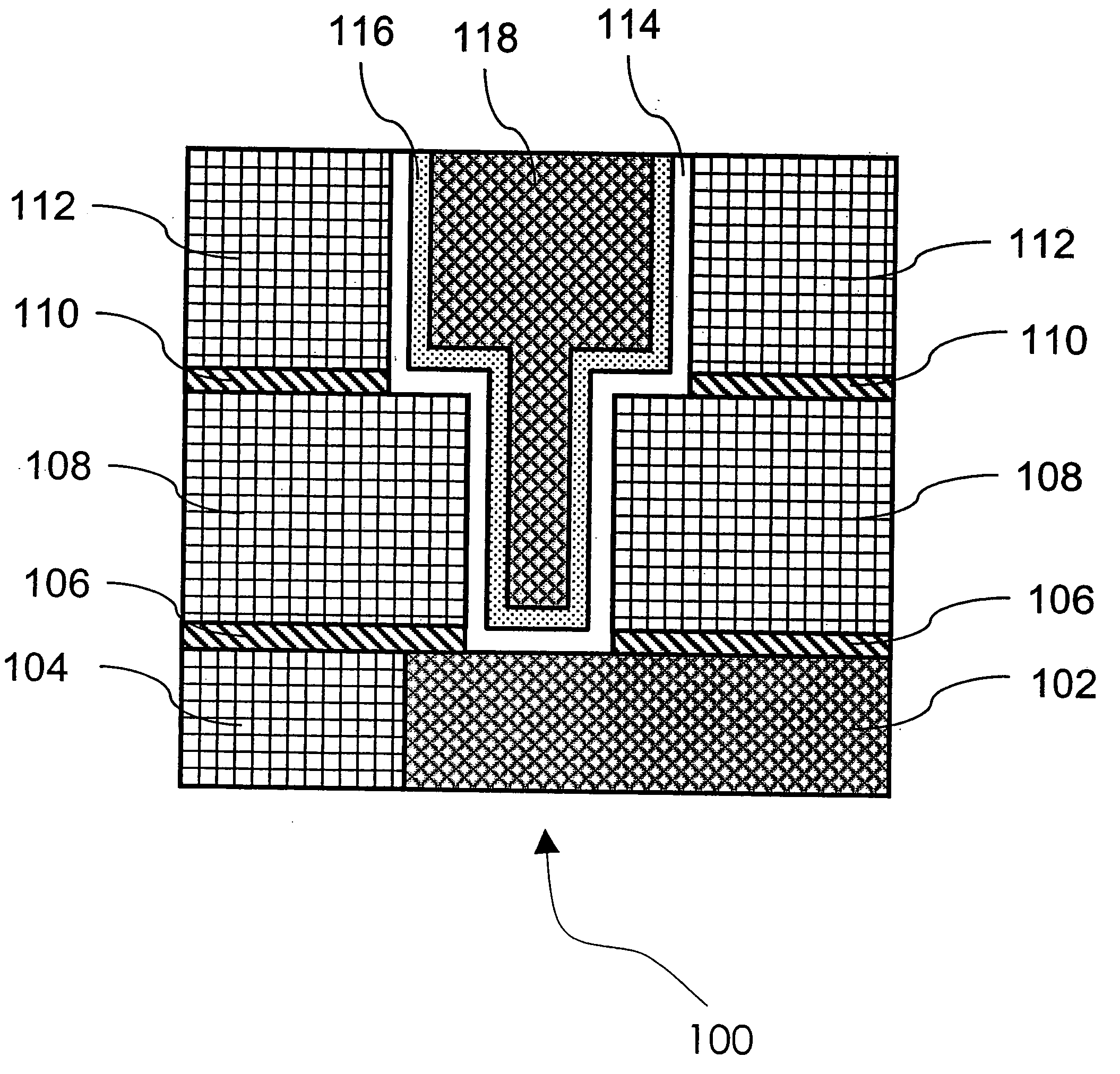
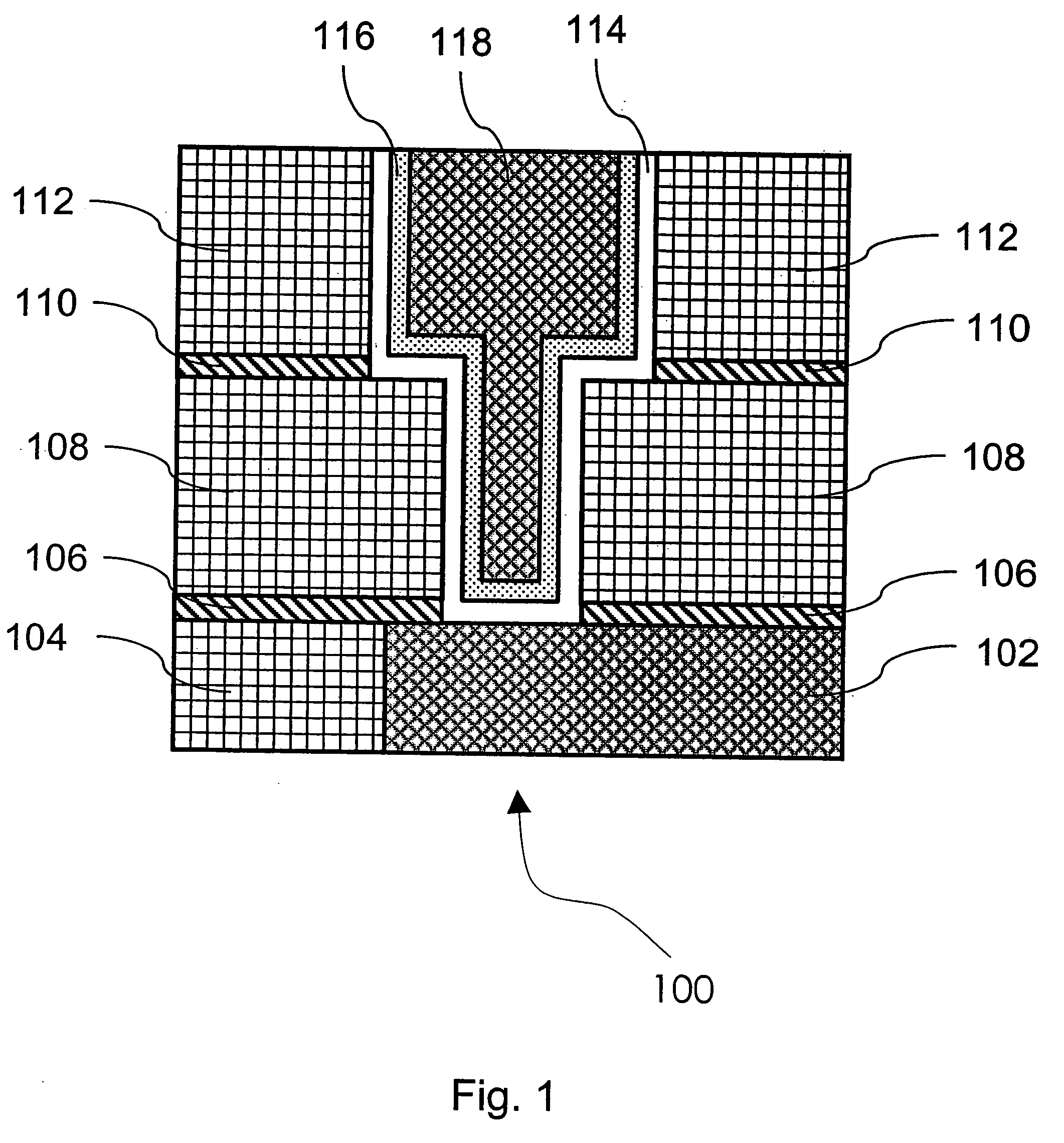
Image

Examples
example 1
[0134] Co(thd)3 and O3 were used as source chemicals for the cobalt oxide deposition in an ALD reactor. Co(thd)3 was heated to 110° C. O3 was prepared from 99.9999% O2 with an external ozone generator. The resulting oxygen source gas mixture consisted of 10-20 vol.- % O3 in O2. Nitrogen, evaporated from liquid nitrogen, was used as an inert purging gas. Co(thd)3 pulse length varied from 1.5 s to 2.0 s, while O3 pulse (flow rate 100 std.cm3 / min) length varied from 2.0 s to 4.0 s. Silicon was used as the substrate material. Substrate temperatures between 150° C. and 350° C. were tested. One pulsing cycle consisted of four sequential steps: Co(thd)3 pulse, N2 purge, O3 pulse, N2 purge.
[0135] The higher deposition temperature tested resulted in uncontrolled film growth, as Co(thd)3 decomposed thermally thus producing a poor thickness profile for the thin film. At the lower substrate temperatures, a controlled growth rate of the thin film (0.3 Å / cycle) and good adhes...
example 2
[0136] Substrates with Si, TiN, WN, W3C and SiO2 surfaces were loaded into an F-120 ALD reactor manufactured by ASM Microchemistry Ltd., Finland. Pd(thd)3 was loaded into a solid source tube of the reactor. The reactor was pumped to vacuum. The pressure of the reaction chamber was adjusted to about 5-10 mbar with flowing nitrogen gas while the pumping of the reactor continued. The Pd(thd)3 was heated to 110° C. and the reaction chamber to 150° C.
[0137] One pulsing cycle consisted of four steps in the following order: Pd(thd)3 pulse (2.0 s), N2 purge (1.0 s), O3 pulse (4.0 s), N2 purge (2.0 s).
[0138] The growth rate of palladium oxide from Pd(thd)3 and O3 was 0.15 Å / cycle at 150° C. According to EDS the film consisted of palladium oxide. The film grew on Si, TiN, WN, WXC (tungsten carbide) and SiO2 surfaces and showed good adhesion.
example 3
Thermal Hydrogen as a Reducing Agent for the Reduction of ALD-Grown Copper Oxide
[0139] A silicon substrate having 20 nm of thermal silicon dioxide on the surface was loaded to the reaction space of a Pulsar® 2000 ALCVD™ reactor. The pressure of the reaction space was adjusted to about 1-20 mbar with a vacuum pump and flowing nitrogen gas (claimed purity 99.9999%). The temperature of the reaction space was adjusted to about 300-315° C. Tungsten nitride carbide (WNC) thin film was deposited on the thermal SiO2 from alternate pulses of WF6, NH3 and triethylboron (TEB). The deposition cycle consisted of WF6 pulse 0.25 s, N2 purge 1 s, NH3 pulse 0.75 s, N2 purge 1 s, TEB pulse 0.1 s and N2 purge 1 s. These pulse and purge times serve as examples of suitable values for the deposition process. Typically, pulse and purge times are selected from a range of about 0.05 s-3 s. Depending on the experiment, the deposition cycle was repeated 30-150 times, resulting in a WNC thin film having a thi...
PUM
| Property | Measurement | Unit |
|---|---|---|
| Temperature | aaaaa | aaaaa |
| Temperature | aaaaa | aaaaa |
| Temperature | aaaaa | aaaaa |
Abstract
Description
Claims
Application Information