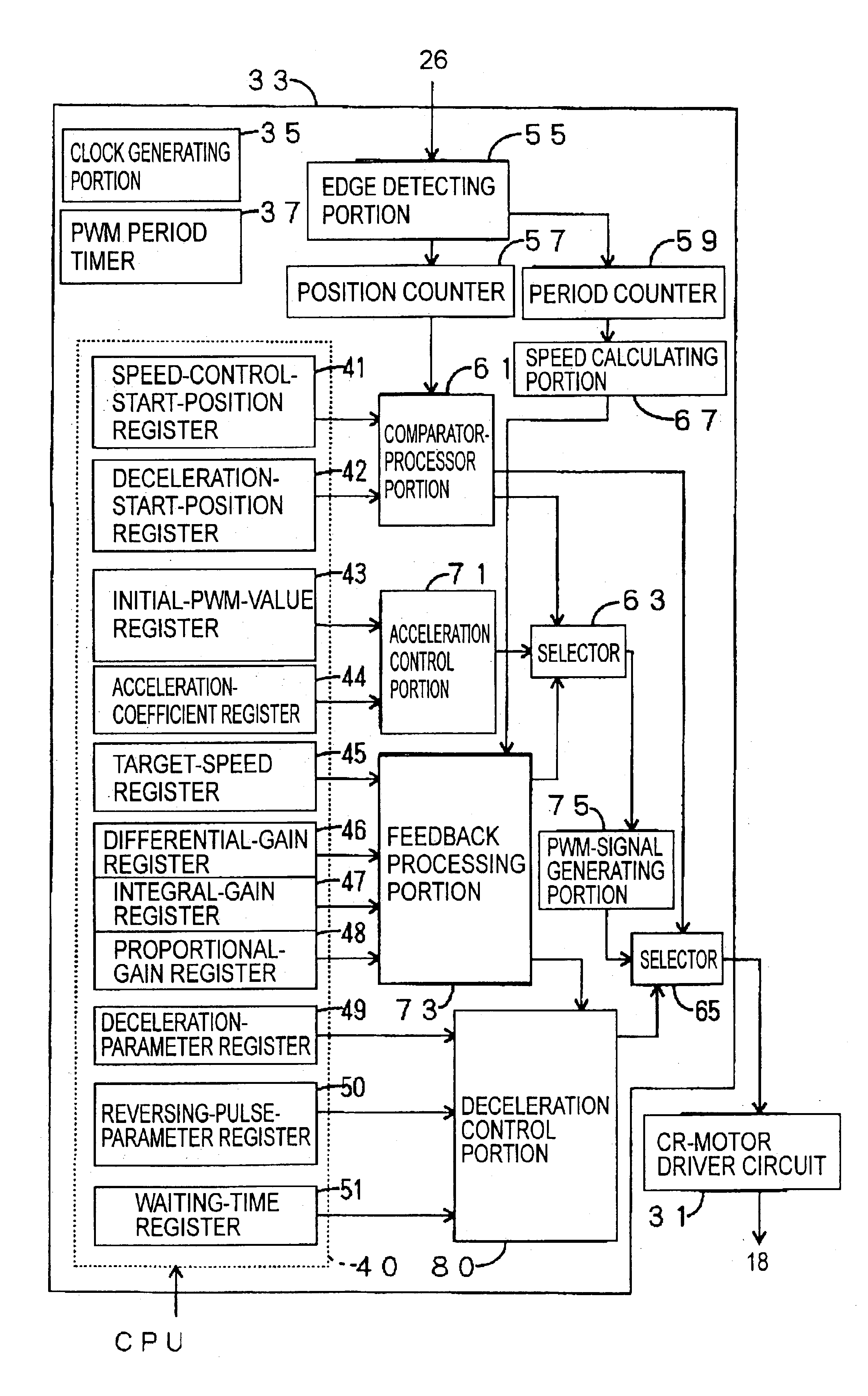
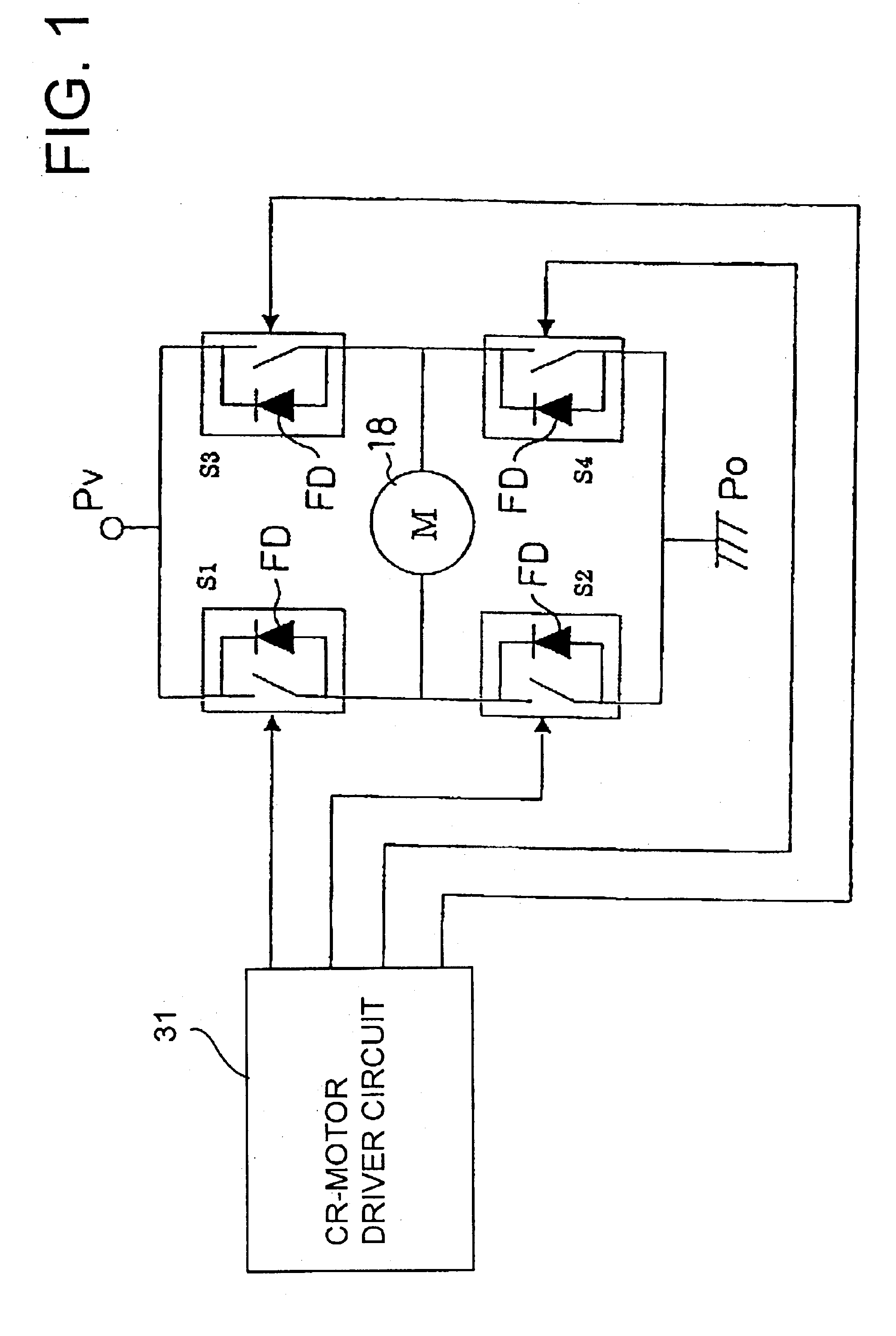
[0016]In the DC-motor deceleration control apparatus constructed according to the above mode (1) of this invention, the forward motor driving means is operated to apply a forward-drive electric current in the form of pulses to the DC motor during its deceleration, and the reverse braking means is operated while the DC motor is subjected to a
regenerative brake or operated in a non-braked state, to apply a reverse-drive electric current in the form of pulses to the DC motor, to apply a plugging brake to the DC motor, such that at least one pulse of the reverse-drive electric current follows every predetermined number of pulses of the forward-drive electric current, and such that the reverse-drive electric current flows in a direction corresponding to a reverse operating direction opposite to the forward operating direction. Thus, the present DC-motor deceleration control apparatus is arranged to apply the forward-drive electric current to the DC motor for smooth deceleration, as well as to apply the reverse-drive electric current to the DC motor for applying a plugging brake to the DC motor so as to shorten the required
deceleration time. Accordingly, the DC motor can be stopped at a desired or nominal position with high positioning accuracy. The term “plugging” used herein is interpreted to mean braking of an
electric motor by reversing its connections, so that the
electric motor tends to turn in the opposite or reverse direction.
[0025]The DC motor can be suitably decelerated even with the application of the forward-drive electric current at the predetermined constant interval, owing to the application of the reverse-drive electric current during interruption of the application of the forward-drive electric current. The application of the forward-drive electric current at the constant time interval simplifies control
processing to decelerate the DC motor, and the hardware arrangement for the control
processing. Accordingly, the DC-motor deceleration control apparatus according to the above mode (9) has an
advantage of simplified control and hardware arrangement for controlling the deceleration of the DC motor, and an accordingly reduced cost of manufacture of the apparatus, in addition to the
advantage discussed above with respect to the above mode (1).
[0027]In the DC-motor deceleration control apparatus according to the above mode (10), the pulse width of the reverse-drive electric current has the predetermined proportional relationship with that of the forward-drive electric current, so that the stop position of the DC motor can be easily controlled. For instance, the pulse width of the reverse-drive electric current is made smaller than that of the forward-drive electric current such that a ratio of these two pulse widths is held constant at a suitable value. In this case, it is possible to prevent an actual operation of the DC motor in the reverse operating direction and an abrupt change in the
operating speed of the DC motor, and assure highly accurate control of the stop position of the DC motor, without having to monitoring an amount of the electric current flowing through the DC motor. Thus, the apparatus according to the above mode (10) is advantageous for its improved control accuracy of the stop position of the DC motor.
[0030]If the reverse-drive electric current is applied to the DC motor immediately after the
initiation of application the
regenerative brake to the DC motor, there may arise a sudden change in the
operating speed of the DC motor. Further, the stop position of the DC motor can be controlled with higher accuracy, when the reverse-drive electric current is not applied up to a moment immediately before the termination of application of the regenerative brake. In the DC-motor deceleration control apparatus according to the above mode (12) wherein the reverse-drive electric current is not applied to the DC motor immediately after the
initiation and before the termination of application of the regenerative brake, the accuracy of control of the stop position of the DC motor can be significantly improved.
[0032]If the applications of the forward-drive electric current and the reverse-drive electric current follow each other, without a time interval therebetween, there may arise problems due to a difference in the switching speeds between the forward motor driving means and the plugging-braking means. The problems include a failure of the electric current to flow through the DC motor, namely, a flow of the electric current between switching elements of the forward motor driving means and / or the plugging-braking means, some other unstable operating behaviors of the DC motor, and breakage or destruction of the switching elements in the worst case. In the apparatus according to the above mode (13), there are provided time intervals between the moment of termination of the application of the forward-drive electric current and the moment of
initiation of the application of the reverse-drive electric current, and between the moment of termination of the application of the reverse-drive electric current and the moment of initiation of the next application of the forward-drive electric current. Accordingly, the present apparatus is effective to prevent breakage of the switching elements, and unexpected application of a dynamic brake to the DC motor, so that the stop position of the DC motor can be controlled with higher accuracy.
[0035]In the DC-motor deceleration control apparatus constructed according to the above mode (14) of the present invention, the plugging-braking means provided in the apparatus according to the above mode (1) is replaced by the
dynamic braking means for applying a dynamic-brake electric current in the form of pulses to the DC motor, so as to short-circuit the DC motor, to apply a dynamic brake to the DC motor, such that at least one pulse of the dynamic-brake electric current follows every predetermined number of pulses of the forward-drive electric current, so that a
kinetic energy of the DC motor is converted into an
electric energy, which is dissipated as heat in the
short circuit. The dynamic brake provides a comparatively large retarding or braking force to be applied to DC motor, so that the DC motor can be smoothly decelerated and can be brought to a stop in a relatively short time, and the stop position of the DC motor can be accurately controlled.


