
Methods and apparatus for delay circuit

a delay circuit and delay technology, applied in the field of electronic circuits, can solve the problems of dlls and plls, affecting the coordination between the system clock and the output signal, and requiring a relatively long time to lock onto the input signal,

Inactive Publication Date: 2005-08-16
ROUND ROCK RES LLC
View PDF7 Cites 40 Cited by
  • Summary
  • Abstract
  • Description
  • Claims
  • Application Information

AI Technical Summary

Benefits of technology

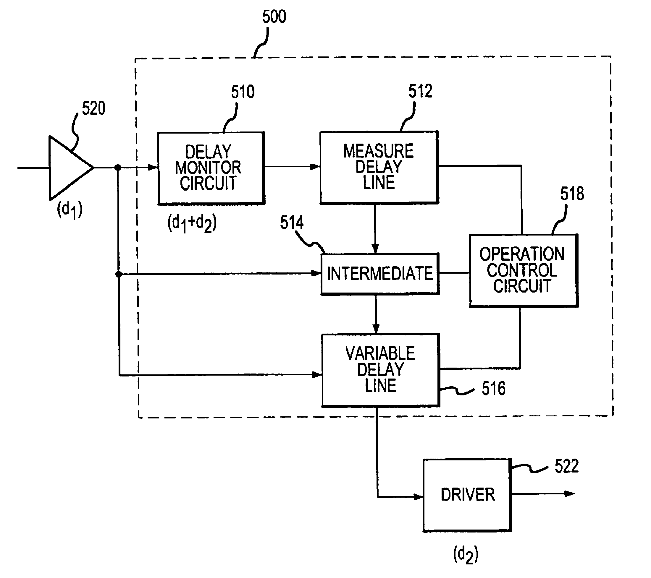
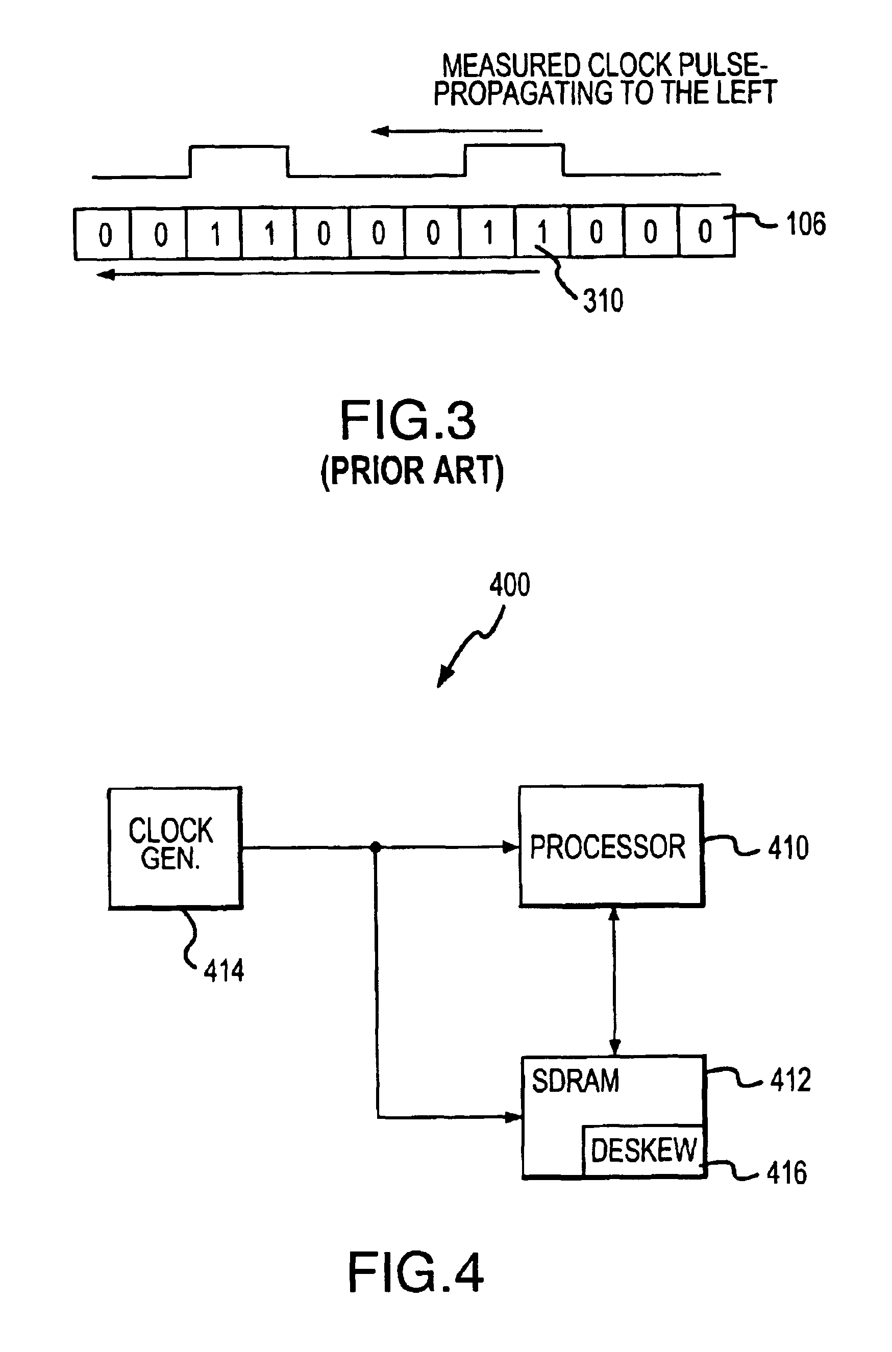
[0009]An electronic system according to various aspects of the present invention includes a deskewing circuit. The deskewing circuit is configured to measure a delay and generate a synchronized signal according to the measured delay. In addition, the deskewing circuit is configured to detect an overflow condition and respond accordingly, for example by asserting an overflow signal. Further, the deskewing circuit may be additionally or alternatively configured to detect successful measurement of the delay and respond, for example by executing a power saving and / or noise reducing procedure.

Problems solved by technology

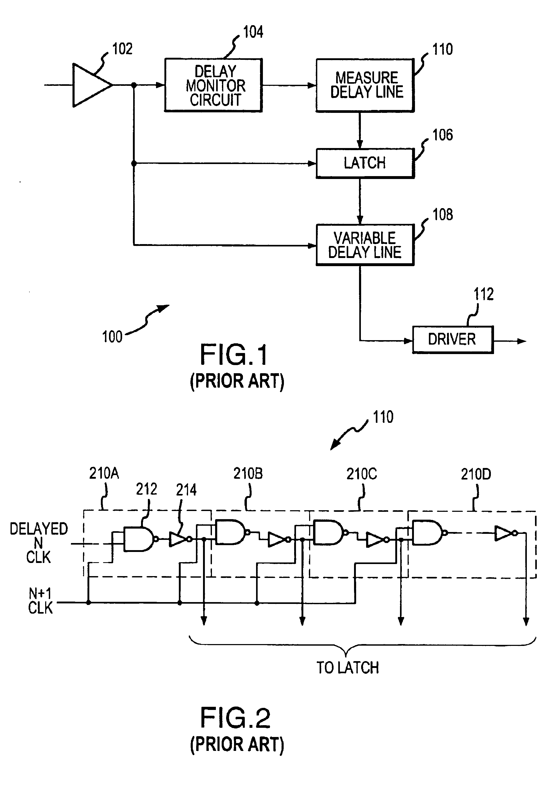
Clock skew, however, disrupts the coordination between the system clock and the output signal of the SDRAM.
Clock skew is a delay between the externally-supplied system clock signal and the signal used by the SDRAM output circuitry to generate the output signals.
Several causes, including delays associated with the clock input buffer, drivers, and other resistive-capacitive circuit elements, contribute to clock skew.
DLLs and PLLs, however, require a relatively long time to lock onto the input signal.
Further, temperature and voltage variations may degrade the performance of DLLs and PLLs.
In some applications, such as portable battery-driven devices, synchronized delay circuits may consume excessive power and / or generate noise.
The additional power consumption and noise generation is due to portions of the digital delay elements toggling unnecessarily.
For especially slow frequencies, the sampling frequency of the synchronized delay circuit may be so high that all of the samples are taken before the first pulse of the input signal arrives, causing an overflow condition.
In other words, the synchronized delay circuit cannot measure a delay exceeding a particular limit.

Method used


Image

  • Methods and apparatus for delay circuit
  • Methods and apparatus for delay circuit
  • Methods and apparatus for delay circuit

Examples


Embodiment Construction

[0024]Various aspects and features of the present invention may be described in terms of functional components and steps. Such functional components and steps may be realized by any number of elements and / or steps configured to perform the specified functions. For example, the present methods and apparatus may employ electronic, signaling, and logic elements, like latches, registers, delay lines, and logic gates, which may carry out a variety of functions in various embodiments, applications, and environments. In addition, the present methods and apparatus may be practiced in conjunction with any number of procedures and systems, and the apparatus and methods described are merely exemplary applications for the invention. Further, the present methods and apparatus may employ any number of techniques, conventional or otherwise, for placement, use, manufacturing, and the like.

[0025]An electronic system according to various aspects of the present invention includes a plurality of compon...


PUM


Abstract

An electronic system includes a deskewing circuit configured to measure a delay and generate a synchronized signal according to the measured delay. The deskewing circuit may be configured to detect an overflow condition and respond accordingly, for example by asserting an overflow signal. Further, the deskewing circuit may be additionally or alternatively configured to detect successful measurement of the delay and respond, for example by executing a power saving and / or noise reducing procedure.

Description

FIELD OF INVENTION[0001]The present invention generally relates to electronic circuits.BACKGROUND OF THE INVENTION[0002]Many electronic devices use clock signals to coordinate operation of components. For example, electronic systems using synchronous dynamic random access memories (SDRAMs) commonly coordinate the SDRAM output with the system clock. Consequently, most SDRAMs and other components receive the system clock for synchronizing the SDRAMs' operations with the other components in the system.[0003]Clock skew, however, disrupts the coordination between the system clock and the output signal of the SDRAM. Clock skew is a delay between the externally-supplied system clock signal and the signal used by the SDRAM output circuitry to generate the output signals. Several causes, including delays associated with the clock input buffer, drivers, and other resistive-capacitive circuit elements, contribute to clock skew.[0004]Several solutions can correct clock skew to coordinate the sy...

Claims


Application Information

Patent Timeline
Patent Type & Authority Patents(United States)
IPC IPC(8): H03K5/135G11C7/22G06F12/00G11C11/407
CPCG11C7/22H03K5/135G11C7/222
Inventor LIN, FENGGOMM, TYLER J.
Owner ROUND ROCK RES LLC
Learn More