
Micromechanical resonator having short support beams

a micromechanical and support beam technology, applied in the direction of device details, device material selection, piezoelectric/electrostrictive device details, etc., can solve the problems of limited use of clamped-clamped resonators, inability to maintain a suitably high quality factor, and not to operate at the same frequency. , to achieve the effect of increasing the resonant frequency, increasing the temperature, and decreasing the electrical stiffness of the resonator

Inactive Publication Date: 2005-08-16
MICREL
View PDF7 Cites 88 Cited by
  • Summary
  • Abstract
  • Description
  • Claims
  • Application Information

AI Technical Summary

Benefits of technology

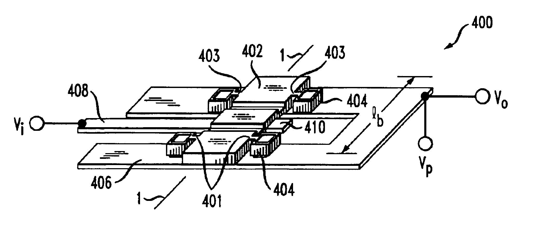
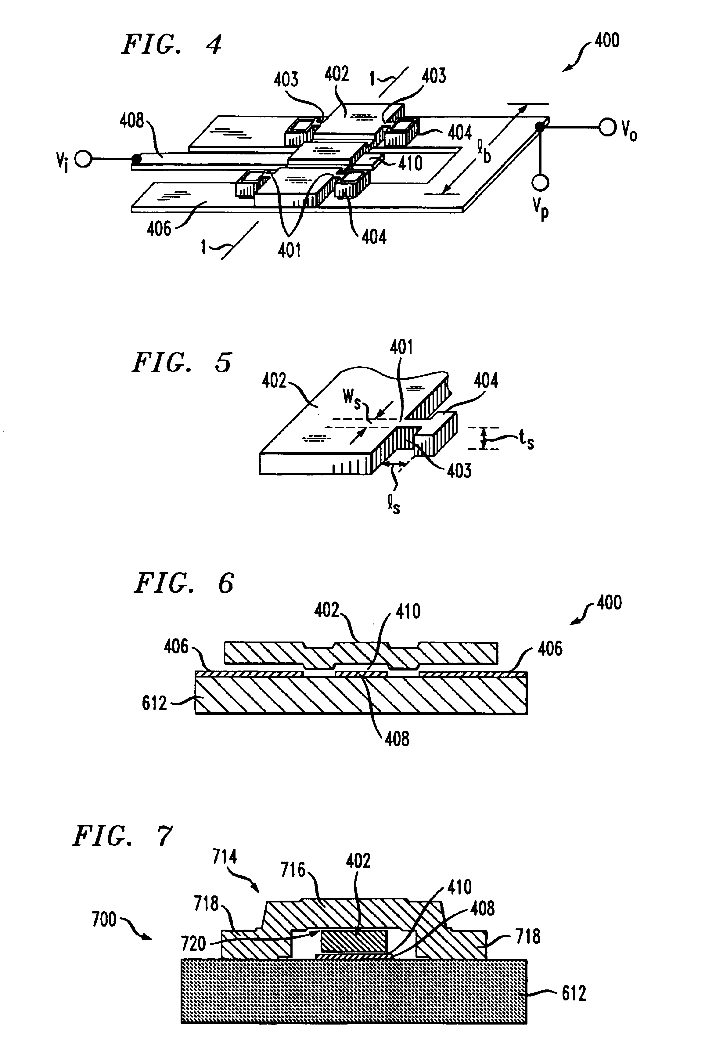
"The present invention is a vertical-mode, free-free beam resonator with micromechanical circuits that includes one or more such resonators. The length of each support (which supports the resonating element) is substantially less than one-quarter of a wavelength of the resonant frequency of the resonator. This reduction in length has been found to have a minimal impact on the quality factor, Q, of the resonator. The resonators are also less susceptible to pull-in or pull down, which is a direct result of the shorter supports. The reduced size of the supports provides a number of benefits, including an increase in resonant frequency, no penalty in power handling capabilities, and a decrease in vacuum requirements. The resonator can also compensate for temperature-induced shifts in resonant frequency, providing temperature stability."

Problems solved by technology

The challenge is to maintain an acceptably-high Q at these frequencies.
But the utility of clamped-clamped resonators is limited.
This limitation pertains not to operating frequency, but rather to an inability to maintain a suitably high quality factor as operating (resonant) frequency increases.
But this approach disadvantageously sacrifices power-handling capability or dynamic range, so that it might prove to be unworkable in certain situations, such as for communications applications in which co-site interference is a problem.
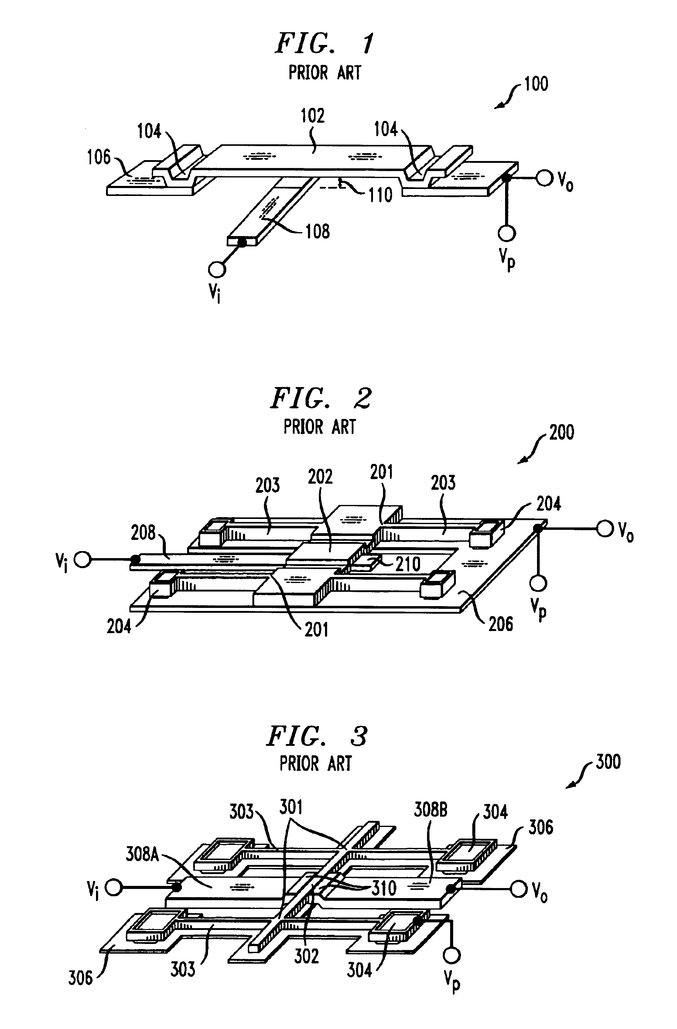
Some of the key drawbacks of this resonator are related to its vertical mode (i.e., “up and down”) of operation.
It is apparent, then, that each resonator described above has drawbacks that limit its utility.

Method used


Image

  • Micromechanical resonator having short support beams
  • Micromechanical resonator having short support beams
  • Micromechanical resonator having short support beams

Examples


Embodiment Construction

[0059]The following references provide information that can be used in the design and fabrication of the illustrative embodiments of the present invention. Each of these references is incorporated herein in their entirety:[0060]U.S. Pat. Nos. 6,249,073 B1, 6,169,321, and 5,976,994.[0061]Publ. U.S. Pat. Apps. US 2002 / 0070816 A1 and US 2003 / 0051550 A1.[0062]Nguyen et al., “Micromachined Devices for Wireless Telecommunications,”Proc. IEEE, v.(86), no.8, pp. 1756-1768 (August 1998).[0063]Wang et al., “VHF Free-Free Beam High-Q Micromechanical Resonators,”Technical Dig., Int'l IEEE Micro Electro Mechanical Systems Conf., Orlando, Fla., pp. 453-458 (Jan. 17-21, 1999).[0064]Nguyen et al., “Frequency-Selective MEMS for Miniaturized Low-Power Communication Device,”IEEE Trans. Microwave Theory Tech., v(47), no.8, pp. 1486-1503 (August 1999).[0065]Bannon et al., “High Frequency Micromechanical Filters,”IEEE J. Solid-State Cir., v(35), n. 4, pp. 512-526 (April 2000).[0066]Nguyen et al., “Transc...


PUM


Abstract

The illustrative embodiment of the present invention is a vertical-mode, free-free beam resonator, and micromechanical circuits that include one or more such resonators. In accordance with the illustrative embodiment, the resonator comprises a movable beam that overlies a drive electrode. The movable beam is supported by a plurality of supports, the length of which is substantially less than one-quarter of a wavelength of the resonant frequency of the resonator.

Description

FIELD OF THE INVENTION[0001]The present invention relates to micromechanical resonators.BACKGROUND OF THE DISCLOSURE[0002]A substantial portion of the circuit-board space of conventional radios (e.g., in cellular phones, etc.) is occupied by off-chip components (e.g., inductors, capacitors, etc.). If all of the components of the radio could be incorporated onto a single chip, the resulting radio would be substantially smaller and more energy efficient than existing radios. To this end, investigators are studying how to create a “single-chip” radio.[0003]Some proposed architectures for the single-chip radio (and interim architectures) include subsystems that incorporate micro-electromechanical systems (“MEMS”) technology. Examples of radio subsystems or “micromechanical circuits” that incorporate MEMS are switches (e.g., for transmit / receive selection; antenna selection, etc.), RF and IF filters, signal processors, and tunable oscillators. The MEMS devices that are used in these subs...

Claims


Application Information

Patent Timeline
Patent Type & Authority Patents(United States)
IPC IPC(8): H03H9/00H03H9/24H03H3/00H03H3/007
CPCH03H3/0072H03H9/2452H03H3/0077H03H2009/02511
Inventor HSU, WAN-THAI
Owner MICREL
Learn More