Liquid crystal display device

a display device and liquid crystal technology, applied in the direction of instruments, static indicating devices, etc., can solve the problems of ten refreshes, ten refreshes, and the response time is greatly delayed in a halftone level, so as to improve the abnormal appearance of colors and suppress color shifts

Inactive Publication Date: 2005-08-16
VIDEOCON GLOBAL
View PDF2 Cites 30 Cited by
  • Summary
  • Abstract
  • Description
  • Claims
  • Application Information

AI Technical Summary

Benefits of technology

[0011]In view of the above technical problems, a feature of the present invention is to suppress color shifts which may occur when any area with a sharp boundary moves and to improve an abnormal appearance of colors at the moving boundary areas.

Problems solved by technology

This is an ideal solution but requires a special liquid crystal with a very high speed response, so that the liquid crystals currently in use are not applicable due to their slow response.
For example, a present TN mode TFT-LCD has its on / off response time of about 1 refresh cycle (16.7 ms at 60 Hz refresh), however, the response time delays greatly in a halftone level, resulting in up to a few to ten refreshes.
In particular, video images of such as TVs or the like mostly have halftone images, so that correct brightness can not be obtained.
Even when displaying text data on PCs, it takes a long time for a screen to become a good condition where one can easily read it when he or she performs a scroll operation.
As above, a deterioration in image quality when displaying moving pictures on a TFT-LCD results from the fact that a transition of brightness of each pixel does not complete within one frame period of 16.7 ms.
Namely, even in the case of liquid crystals with a fast response, the capacitance of the liquid crystal changes based on the principle of driving of the liquid crystal, thus the targeted brightness can not be achieved with only one time of charge / discharge of TFT as long as using the normal driving method.
The overdrive technique allows matching the response time of each sub-pixel to about one frame period, however, it can not accelerate a transition to a full OFF state, i.e., 0V.
When not allowed using a voltage which exceeds the voltage used for statically defined gradations (i.e., overvoltage range), there may occur a case where it is impossible to respond within one frame period in the on-direction transition.
Furthermore, particularly seen in the TN mode liquid crystals, the effective brightness (average brightness) can not be matched within one frame period even by using the overdrive technique because the response time changes depending in particular on the starting gradation and targeted gradation.

Method used


Image

  • Liquid crystal display device
  • Liquid crystal display device
  • Liquid crystal display device

Examples


Embodiment Construction

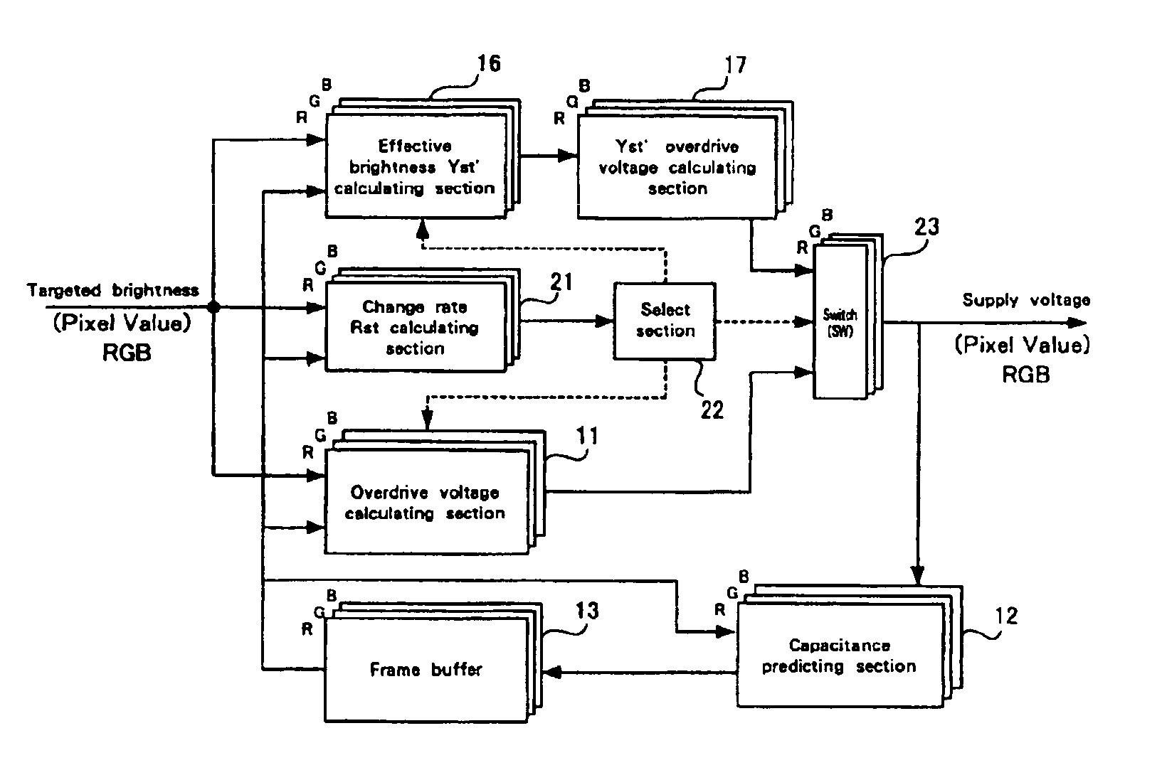
[0030]Moreover, a controller of the present invention further includes a capacitance predicting unit for predicting a capacitance value of a pixel that will be reached after the refresh cycle when applying the voltage calculated by the voltage calculating unit to the pixel with the present capacitance value; and a storage device for storing the capacitance value predicted by the capacitance predicting unit.

[0031]Now the present invention will be described with reference to the accompanying drawings.

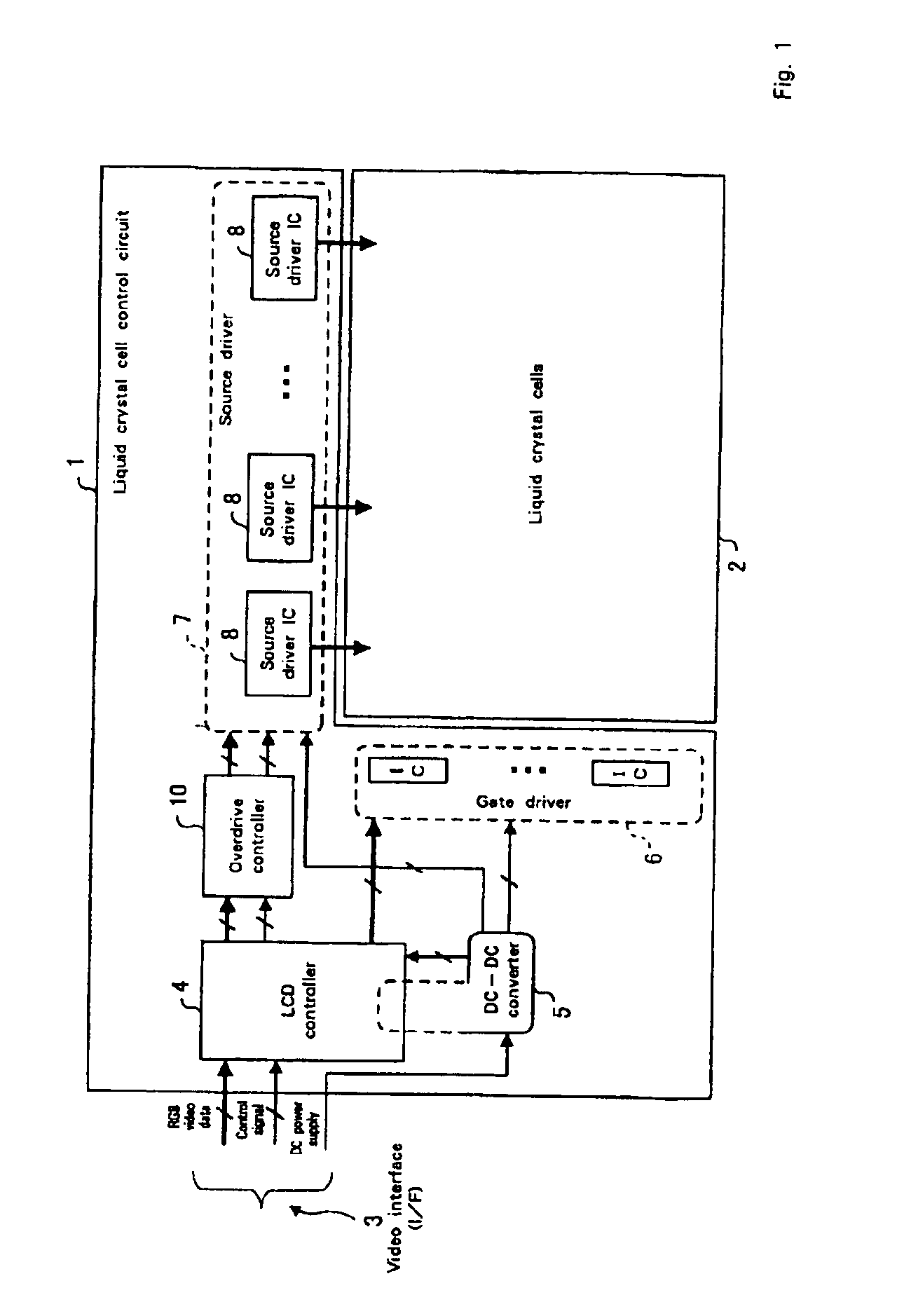
[0032]FIG. 1 is a schematic diagram of an embodiment of a liquid crystal display (LCD) device according to the present invention. As for the LCD device shown in FIG. 1, a liquid crystal module (LCD panel) is composed of a liquid crystal cell control circuit 1 and a liquid crystal cell 2 with a liquid crystal structure of thin film transistors (TFT). The liquid crystal module is formed in a display device separated from a system unit on the host's side such as a personal computer (PC) and ...


PUM

PropertyMeasurementUnit
response timeaaaaaaaaaa
withstand voltageaaaaaaaaaa
voltageaaaaaaaaaa

Abstract

An overdrive controller for driving a liquid crystal display includes a change rate Rst calculating section for comprehending a transition state from a present brightness to a targeted brightness for each of R, G and B sub-pixels, a select section for selecting the sub-pixel with the slowest transition and the other sub-pixels from the comprehended transition states, and an overdrive voltage calculating section for calculating a voltage to accelerate a transition of brightness for the sub-pixel with the slowest transition. The overdrive controller further includes, an effective brightness Yst′ calculating section and Yst′ overdrive voltage calculating section for calculating a voltage to accelerate or to decelerate a transition of brightness for the other sub-pixels in order to coordination with each other, wherein the voltage is switched by a switch 23 to be supplied.

Description

BACKGROUND OF INVENTION[0001]1. Field of the Invention[0002]The present invention relates to a liquid crystal display device, and more particularly to a liquid crystal display device for improving the problems of response times with regard to a liquid crystal display.[0003]2. Background of the Invention[0004]Recently, a liquid crystal display (LCD) equipped with thin film transistors (TFT) has developed significantly due to its characteristics including light weight, thin shape and low power consumption. Conventionally, the use of LCDs for PCs was mainly directed to displaying static images, however, they have been substituted for CRTs such as when displaying moving pictures in a graphics system or when displaying video images on monitors, so that there is a growing concern about displaying moving pictures using LCDs.[0005]While a CRT is in the impulse type of light emission, an LCD is in the hold type with emitting a continuous light during a whole period of a frame, thus being una...

Claims


Application Information

Patent Timeline
Patent Type & Authority Patents(United States)
IPC IPC(8): G09G3/36G02F1/133G09G3/20
CPCG09G3/2011G09G3/3607G09G3/3648G09G2320/0252G09G2320/0261G09G2340/16
Inventor SEKIYA, KAZUONAKAMURA, HAJIME
Owner VIDEOCON GLOBAL
Why Eureka
Try Eureka