Active matrix type liquid crystal display apparatus

a liquid crystal display and active matrix technology, applied in the direction of liquid crystal compositions, chemistry apparatus and processes, instruments, etc., can solve the problems of reducing brightness, no consideration is given to the configuration of the liquid crystal display apparatus required, and no consideration is given to the characteristic of the light source required to reduce the power consumption of the whole liquid crystal display apparatus, etc., to achieve the effect of fine display characteristic and low power consumption

Inactive Publication Date: 2007-04-24
PANASONIC LIQUID CRYSTAL DISPLAY CO LTD +1
View PDF37 Cites 2 Cited by
  • Summary
  • Abstract
  • Description
  • Claims
  • Application Information

AI Technical Summary

Benefits of technology

[0014]An object of the present invention is to provide an improved liquid crystal display apparatus, in which a low power consumption and a fine display characteristic are compatible with each other.
[0015]Another object of the present invention is to provide an improved liquid crystal display apparatus which can suppress color shift caused by the application of a voltage and reduce the occurrence of a color defect due to a local difference in thickness in the liquid crystal layer.
[0016]A liquid crystal display apparatus according to the present invention comprises a liquid crystal panel having a pair of substrates, a plurality of electrodes formed on at least one of said pair of electrodes and a liquid crystal layer sandwiched between said pair of substrates, and a light source provided on one surface of said liquid crystal panel. The light source has a luminous characteristic with the chromaticity of a warm color family and said liquid crystal panel has a characteristic of spectral transmittance with the chromaticity of a cold color family. Thereby, the color of said light source can be compensated.

Problems solved by technology

However, in a display system of this type wherein the direction of an electric field applied to the liquid crystal is controlled to be parallel with the surface of a substrate by using active elements (hereinafter referred to as a horizontal electric field type), no consideration is given to the characteristic of the light source required to decrease the power consumption of the whole liquid crystal display apparatus.
Further, no consideration is given to the configuration of the liquid crystal display apparatus required to suppress color shift in response to the application of a voltage thereto and to prevent a color defect from occurring.
Because the luminous efficiency of the fluorescent lamp in a short wavelength region is less than that in a long wavelength region, the brightness may be reduced, and so a large consumption of power is required to obtain a high brightness.
Therefore, the liquid crystal display element is easily colored, in other words, it is easy to be unnecessarily colored.
Therefore, the display state of colors is extremely deteriorated.
Because the difference between the thickness of the liquid crystal layers appears as a change in the peak wavelength in the birefringence mode, the local and abnormal thickness of the liquid crystal display layer causes display defects, such as variations in the intensity and / or color tone, which are different from those in its surrounding area.

Method used


Image

  • Active matrix type liquid crystal display apparatus
  • Active matrix type liquid crystal display apparatus
  • Active matrix type liquid crystal display apparatus

Examples


embodiment a

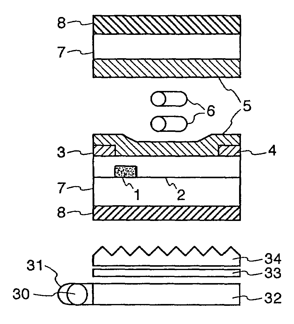
[0140]The liquid crystal display apparatus has two substrates, one of which has a color filter with B, G and R pixels on its surface. A nematic liquid crystal composition is inserted between the substrates, of which the anisotropy of the dielectric constant is positive, +12.0, and the anisotropy of the refractive index is 0.079 (589 nm, 20° C.). The gap d between cells is formed by scattering spherical polymer beads and sandwiching them between the substrates. The gap is adjusted to d=2.87 μm by selecting the radius of the beads.

[0141]In this comparison example, dLC·Δn (589 nm) equals 0.227 μm and dLC·Δn (490 nm) equals 0.232 μm. As a result, deff·Δn (490 nm) equals about 0.21 μm. This value is out of the present invention.

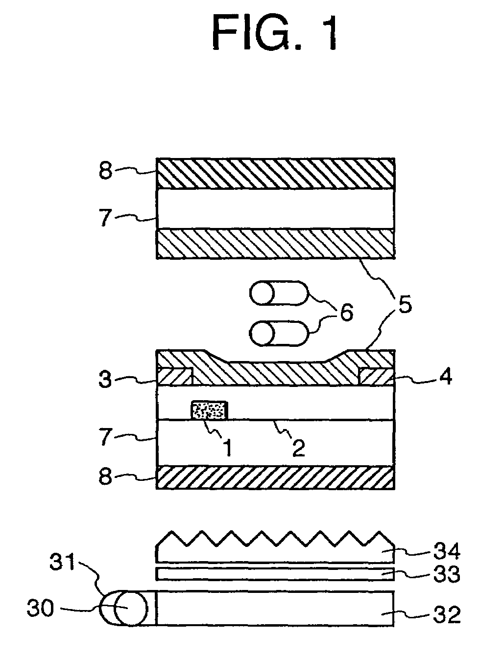
[0142]The liquid crystal display panel is provided with a back-light unit as a light source which has a color temperature of 6818K.

embodiment b

[0143]The liquid crystal display apparatus has two substrates, one of which has a color filter with B, G and R pixels on its surface. A nematic liquid crystal composition is inserted between the substrates, of which the anisotropy of the dielectric constant is positive, +12.0, and the anisotropy of the refractive index is 0.079 (589 nm, 20° C.). The gap d between cells is formed by scattering spherical polymer beads and sandwiching them between the substrates. The gap is adjusted to d=3.17 μm by selecting a radius of the beads which is different from that in embodiment A.

[0144]In this embodiment B, dLC·Δn (589 nm) equals 0.250 μm and dLC·Δn (490 nm) equals 0.256 μm. As a result, deff·Δn (490 nm) equals about 0.23 μm.

[0145]The liquid crystal display panel is provided with a back-light unit as a light source which has a color temperature of 4703K.


PUM

PropertyMeasurementUnit
wavelengthsaaaaaaaaaa

Abstract

A liquid crystal display apparatus having a liquid crystal panel including a pair of substrates, a plurality of electrodes formed on at least one of the pair of substrates and a liquid crystal layer sandwiched between the pair of substrates, and a light source provided on one surface of the liquid crystal panel. An electric field in the liquid crystal layer produced by the plurality of electrodes is predominantly in parallel with surfaces of the pair of substrates. The light source has a luminous characteristic with a first chromaticity and the liquid crystal panel has a characteristic of spectral transmittance with a second chromaticity different from the first chromaticity so as to compensate for the color of the light source.

Description

CROSS REFERENCE TO RELATED APPLICATION[0001]This is a continuation of U.S. application Ser. No. 09 / 572,375, filed May 18, 2000, now U.S. Pat. No. 6,621,538, which is a continuation of U.S. application Ser. No. 08 / 740,008, filed Oct. 23, 1996, now U.S. Pat. No. 6,137,560, the subject matter of which is incorporated by reference herein.BACKGROUND OF THE INVENTION[0002]The present invention relates to a liquid crystal display apparatus, and, more particularly, to an active matrix liquid crystal display apparatus.[0003]Various examples of liquid crystal display apparatus are disclosed, for example, in Japanese Patent Publication No. 63-21907 (1988), UP, WO91 / 10936 and Japanese Patent Application Laid-Open No. 6-222397 (1994), in which a pair of comb electrodes are used to apply an electric field to a liquid crystal in a direction parallel to the surface of a substrate. However, in a display system of this type wherein the direction of an electric field applied to the liquid crystal is c...

Claims


Application Information

Patent Timeline
Patent Type & Authority Patents(United States)
IPC IPC(8): C09K19/02G02F1/13357G02F1/1343
CPCG02F1/133514G02F1/133604G02F1/133609G02F1/133371G02F1/133512G02F1/134363G09G3/3406G09G3/3648G09G2300/0434G09G2320/0242G09G2330/021G02F1/1343G02F1/136
Inventor UTSUMI, YUKAKONDO, KATSUMIHIYAMA, IKUOITOH, OSAMUOHE, MASAHITOYANAGAWA, KAZUHIKOASHIZAWA, KEIICHIRO
Owner PANASONIC LIQUID CRYSTAL DISPLAY CO LTD
Why Eureka
Try Eureka