User interface for monitoring remote devices

a remote device and user interface technology, applied in the field of remote system monitoring, can solve the problems of ineffectiveness of aperiodic monitoring system, preventing consumers from being able to adjust consumption, and inherently inefficient aperiodic monitoring system

a remote device and user interface technology, applied in the field of remote system monitoring, can solve the problems of ineffectiveness of aperiodic monitoring system, preventing consumers from being able to adjust consumption, and inherently inefficient aperiodic monitoring system

US6931445B2Active Publication Date: 2005-08-16LANDISGYR TECH

Image

  • User interface for monitoring remote devices
  • User interface for monitoring remote devices
  • User interface for monitoring remote devices

Examples


Embodiment Construction

[0037]Reference is now made in detail to the description of the invention as illustrated in the drawings. While the invention will be described in connection with these drawings, there is no intent to limit it to the embodiment or embodiments disclosed therein. On the contrary, the intent is to cover all alternatives, modifications and equivalents included within the spirit and scope of the invention as defined by the appended claims.

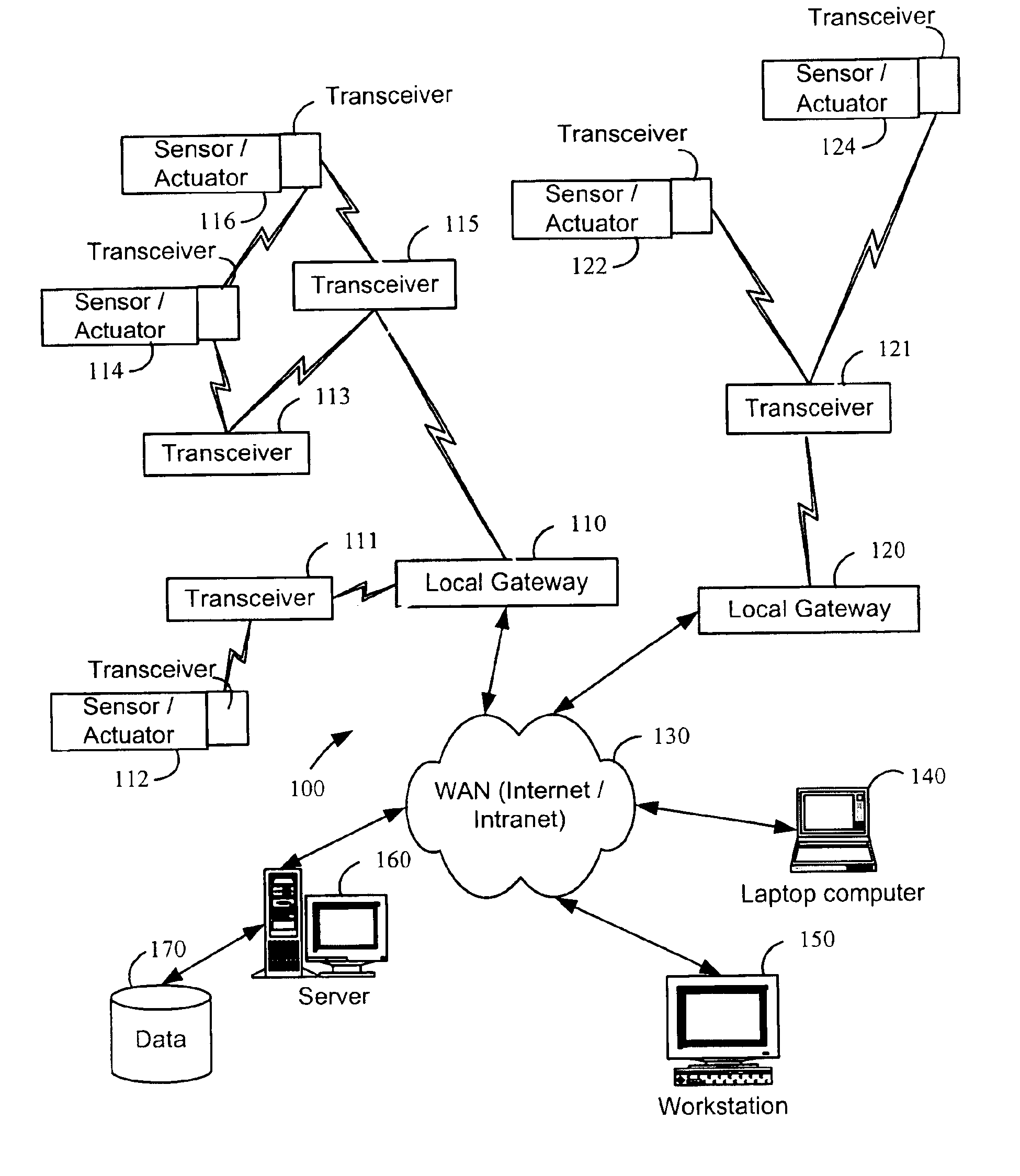
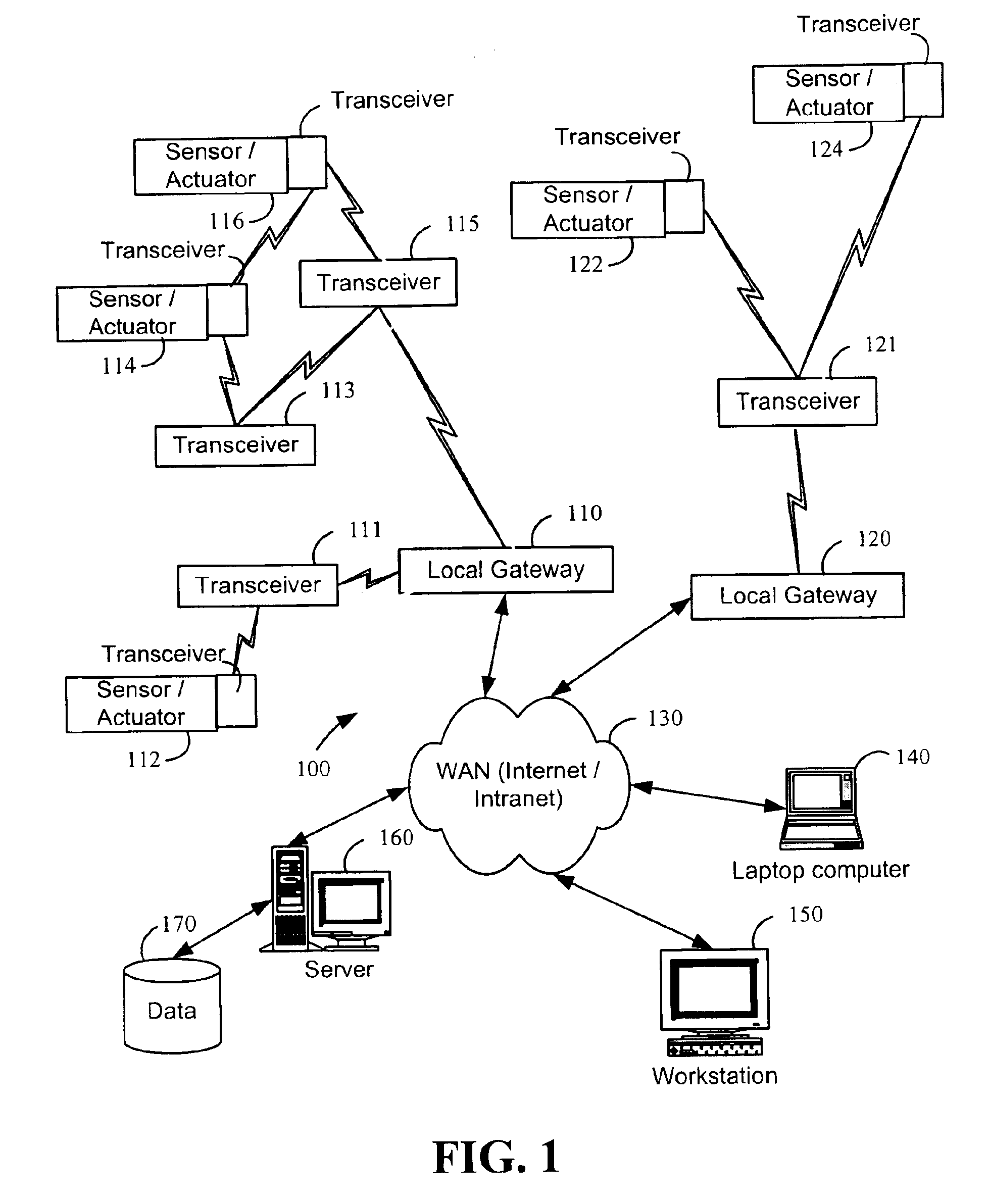
[0038]Reference is now made to FIG. 1, which is a block diagram that illustrates an example of a monitoring system in accordance with the present invention. In depth discussions of various aspects of the monitoring system are not necessary to disclose the present invention, therefore, these aspects will not be addressed in depth herein. Rather, greater detail with regard to the monitoring system 100 can be found in U.S. application Ser. No. 09 / 439,059, which is incorporated herein by reference in its entirety. Monitoring system 100 consists of one or mo...


PUM


Abstract

A system for monitoring utility consumption information, the system including a memory to store utility consumption information and a processor configured by the memory to provide a user interface to enable an user to view the utility consumption information in a time-segmented fashion.

Description

BACKGROUND OF THE INVENTION[0001]1. Field of the Invention[0002]The present invention generally relates to remotely operated systems, and more particularly to a computerized system for monitoring remote systems by transferring information signals through a wide area network (WAN) and using software applications hosted on a connected server to generate the information for display.[0003]2. Discussion of the Related Art[0004]As is known, there are a variety of systems for monitoring and controlling manufacturing processes, inventory systems, emergency control systems, and the like. Most automatic systems use remote sensors and controllers to monitor and automatically respond to system parameters to reach desired results. A number of control systems utilize computers to process system inputs, model system responses, and control actuators to implement process corrections within the system. Both the electric power generation and metallurgical processing industries have had success control...

Claims


Application Information

Patent Timeline
16 Aug 2005
Publication
US6931445B2
IPC
G06F15/16; G06F15/173; G06K; H02J13/00
CPC
H02J13/0075; H04Q9/00; Y04S40/126; H04Q2209/60; Y02E60/7853; Y04S10/30; Y02E60/74; H02J13/00002
Inventors
DAVIS, JAMES S.