
Device for in-line measurement of properties of fluid flows in pipeline systems

a technology of fluid flow and pipeline system, which is applied in the direction of volume measurement apparatus/methods, speed/acceleration/shock instrument details, measurement apparatus housings, etc., can solve the problems of pipeline system clogging and inoperative, pipeline system not suitable for transporting solids, and pipeline system not suitable for paste or slurry

Inactive Publication Date: 2005-08-23
CANADA MINING IND RES ORG
View PDF25 Cites 44 Cited by
  • Summary
  • Abstract
  • Description
  • Claims
  • Application Information

AI Technical Summary

Benefits of technology

[0005]It is an object of the present invention to provide a device (herein called a “pill”) which will freely travel within the fluid transported by pipeline, including solids transport pipeline systems, and effect scans of desired properties, characteristics or phenomena during such travel at a predetermined rate.
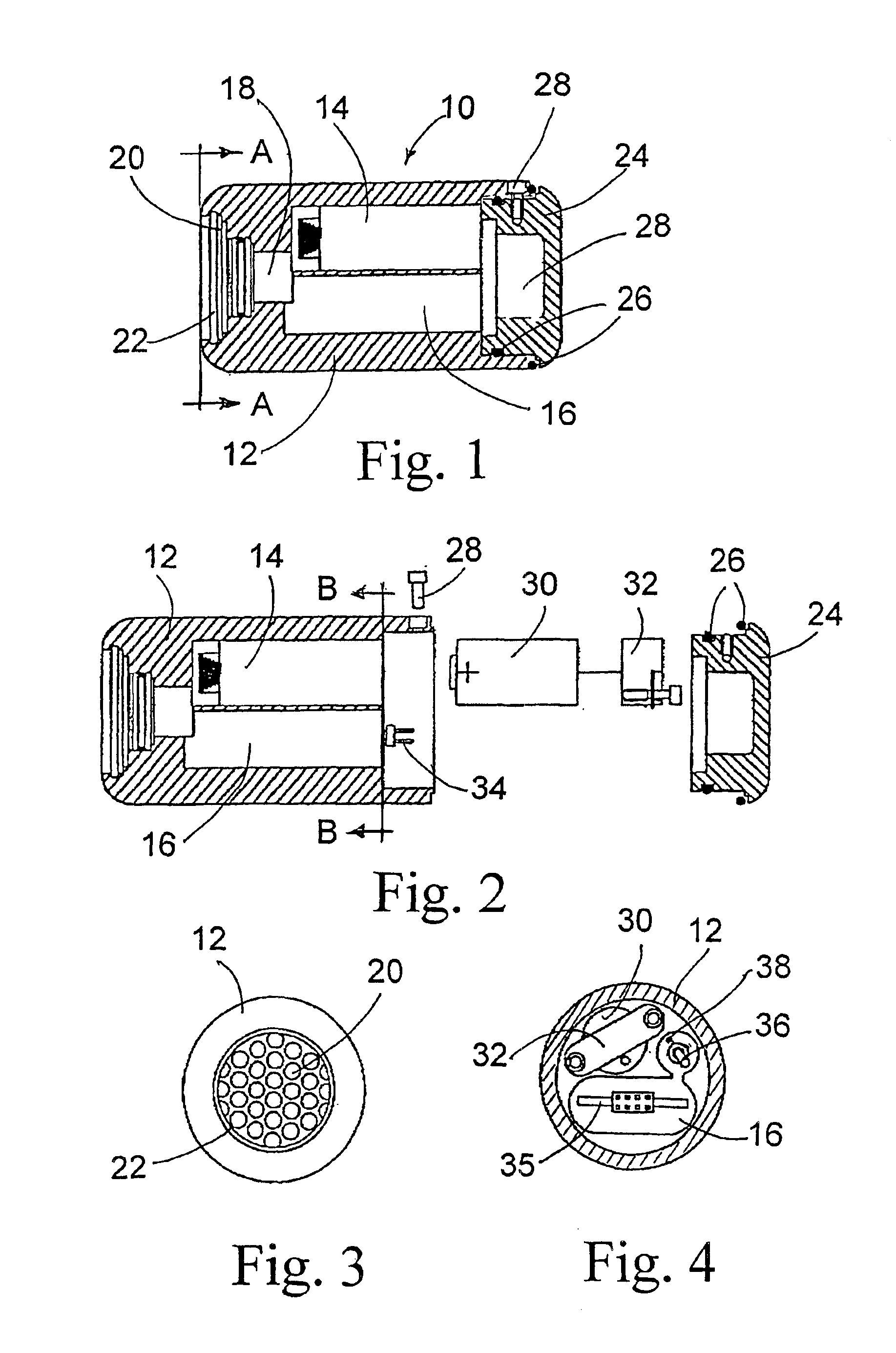
[0012]Also, the electronics normally include an A / D converter and a thermistor to compensate for the temperature variation. The sampling rate is user defined and may, for example, range from 10 scans per second to only a few scans during the entire residence time of the pill in the pipeline. The data output may be configured to display either unprocessed integers or computed values. Logged data may be downloaded to a PC using any basic terminal program. Such data may then be compared to the system's layout and allow the operator to quickly calculate friction loss, or deduce anomalies in the system. The system can thus be handled with the knowledge of the factual rheological data for every section of the transporting pipeline.

Problems solved by technology

They would not be suitable for pipelines transporting solids where they would quickly become clogged and inoperative.
Again, such device takes up essentially the entire circumferential space within the pipeline as it travels and it would not be suitable for paste or slurry pipeline systems where it would be quickly damaged.
A considerable amount of effort and money has been spend to identify and remedy the cause and effect of water-hammer, cascades, impact points, adiabatic heating and the effects of vugs, vacuums, line restrictions and pressure spikes during mining backfill operations.
Similar problems arise in other solids transport systems, such as used for concrete piping and the transport of other pastes or slurries.

Method used


Image

  • Device for in-line measurement of properties of fluid flows in pipeline systems
  • Device for in-line measurement of properties of fluid flows in pipeline systems
  • Device for in-line measurement of properties of fluid flows in pipeline systems

Examples


Embodiment Construction

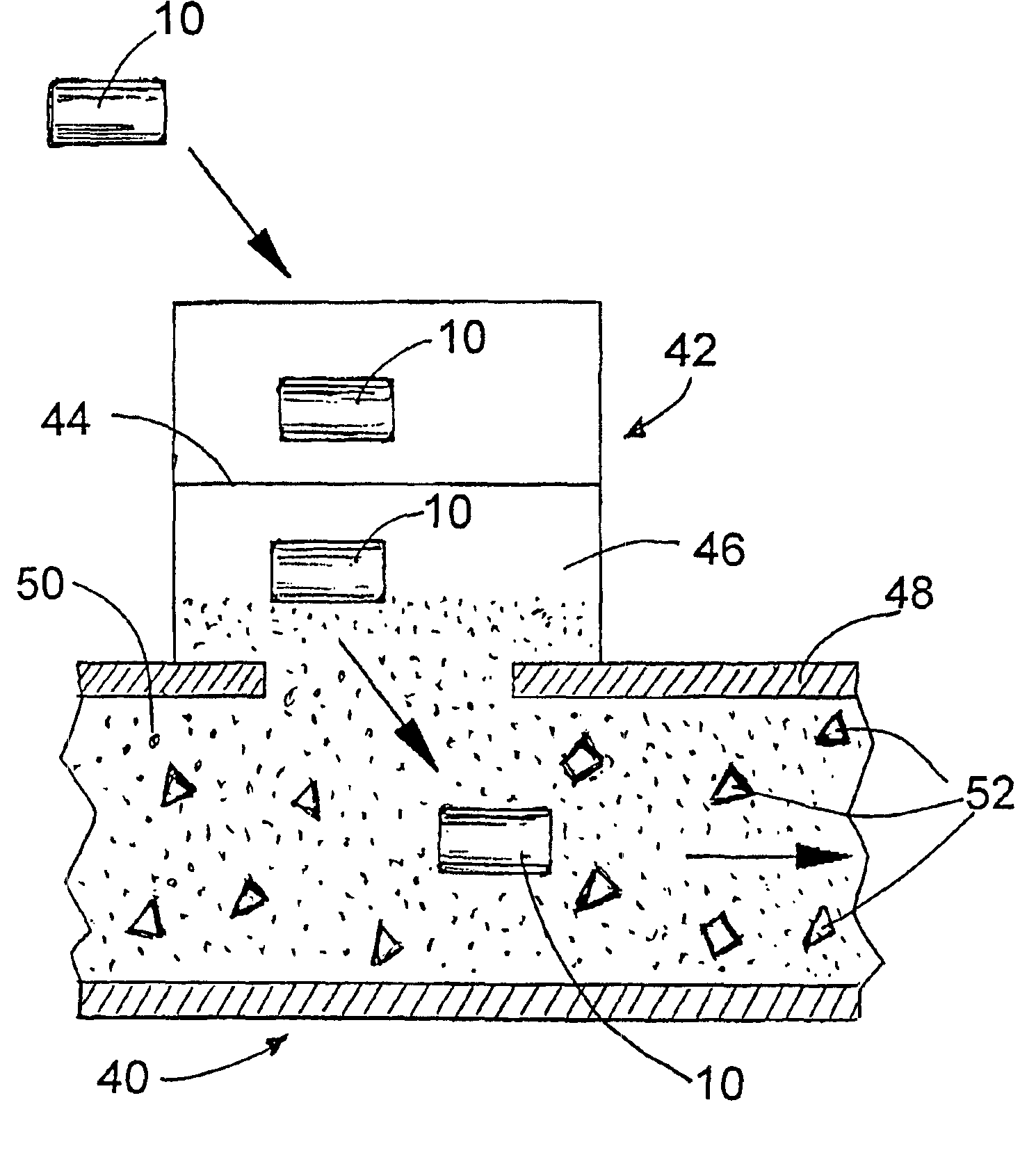
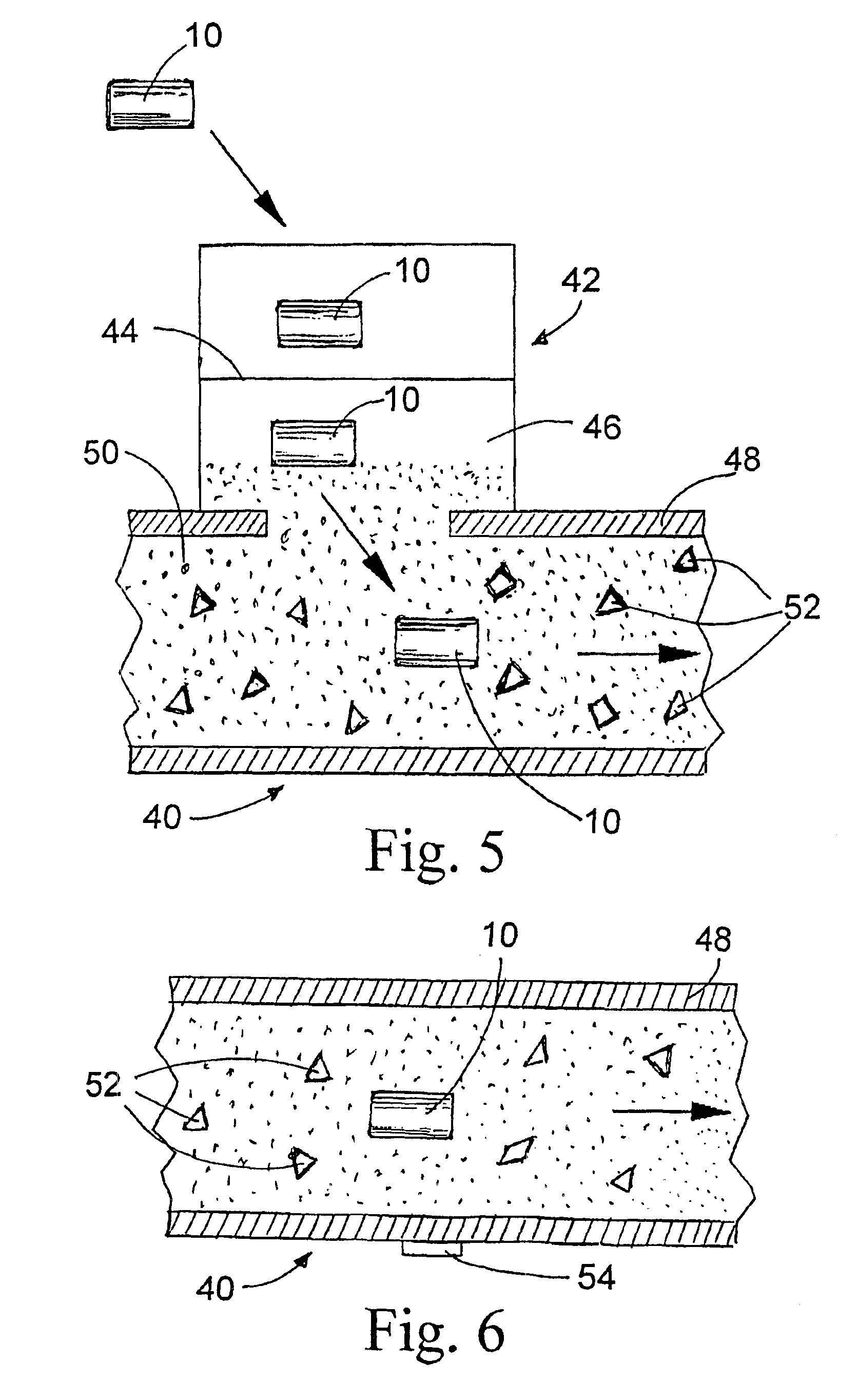
[0021]Referring to the drawings in which the same elements are designated by the same reference numbers, FIG. 1 illustrates the novel device or pill 10. The dimensions of the pill could be those actually shown in FIG. 1, although the pill is not limited to any specific dimensions and, for example, smaller dimensions than those shown in FIG. 1, could be used. The pill 10 comprises a housing 12, which can be made of aluminum, stainless steel or any other suitable material, with space 14 within the housing being reserved for a power source, such as a battery, and space 16 for the electronics package. At the front end of the housing 12, there is provided a sensor 18 which extends outwardly and is protected by a protective mesh 20 held in place by a retaining ring 22. At the rear end, housing 12 is closed with an end cap 24 which provides a watertight closure by means of O-rings 26 and screw 28.

[0022]Within the end cap 24, there is provided a space 28 which acts as a buoyancy compensator...


PUM


Abstract

A device called “pill” is provided for in-line measurement of properties, such as pressure and temperature, in a fluid flow within a pipeline system. The device is small enough to travel in the medium of the pipeline system in an unrestricted manner. It has at least one sensor to scan properties such as pressure and temperature at a desired rate. Also, the device includes a microprocessor for logging data scanned by the sensor so that it can later be downloaded and analysed by a PC. Moreover, the device has a buoyancy compensator for adjusting the specific gravity of the device to make it compatible with the medium in which it travels. The novel device is particularly suitable for use in solids transport systems, such as mining backfill systems.

Description

FIELD OF THE INVENTION[0001]This invention relates to a device for measuring properties and phenomena, such as pressure and temperature, of fluid flows in pipeline systems, particularly in solids transport pipeline systems, such as mining backfill systems, concrete piping systems and similar paste and slurry systems. More specifically, it relates to a device which travels within the pipeline with the flow of the fluid, paste or slurry and scans the desired properties and flow characteristics at a predetermined rate, as well as stores them for subsequent computer readout and analysis.BACKGROUND OF THE INVENTION[0002]There are a number of devices known in the art, usually called “pigs”, which are adapted to travel through the pipeline with the fluids, such as crude oil, and measure pressure drops in the pipeline to detect leaks therein. Examples of such devices are disclosed in U.S. Pat. Nos. 3,974,680 and 4,020,674. Such pigs are large devices encompassing essentially the entire inte...

Claims


Application Information

Patent Timeline
IPC IPC(8): G01L19/00G01L19/08G01L5/00G01M3/24G01M3/00
CPCG01L5/008G01L19/083G01M3/005
Inventor RANTALA, PAUL A.MACKENZIE, ANDREW T.
Owner CANADA MINING IND RES ORG
Learn More