
Gripping mechanisms, apparatus, and methods

a technology of gripping mechanism and gripping device, applied in the direction of load-engaging elements, thin material handling, instruments, etc., can solve the problems of biased assay, sample being dispensed into an incorrect well, human distraction and error, etc., and achieve the effect of reducing friction and reducing friction

Inactive Publication Date: 2005-08-23
NOVARTIS AG
View PDF48 Cites 37 Cited by
  • Summary
  • Abstract
  • Description
  • Claims
  • Application Information

AI Technical Summary

Benefits of technology

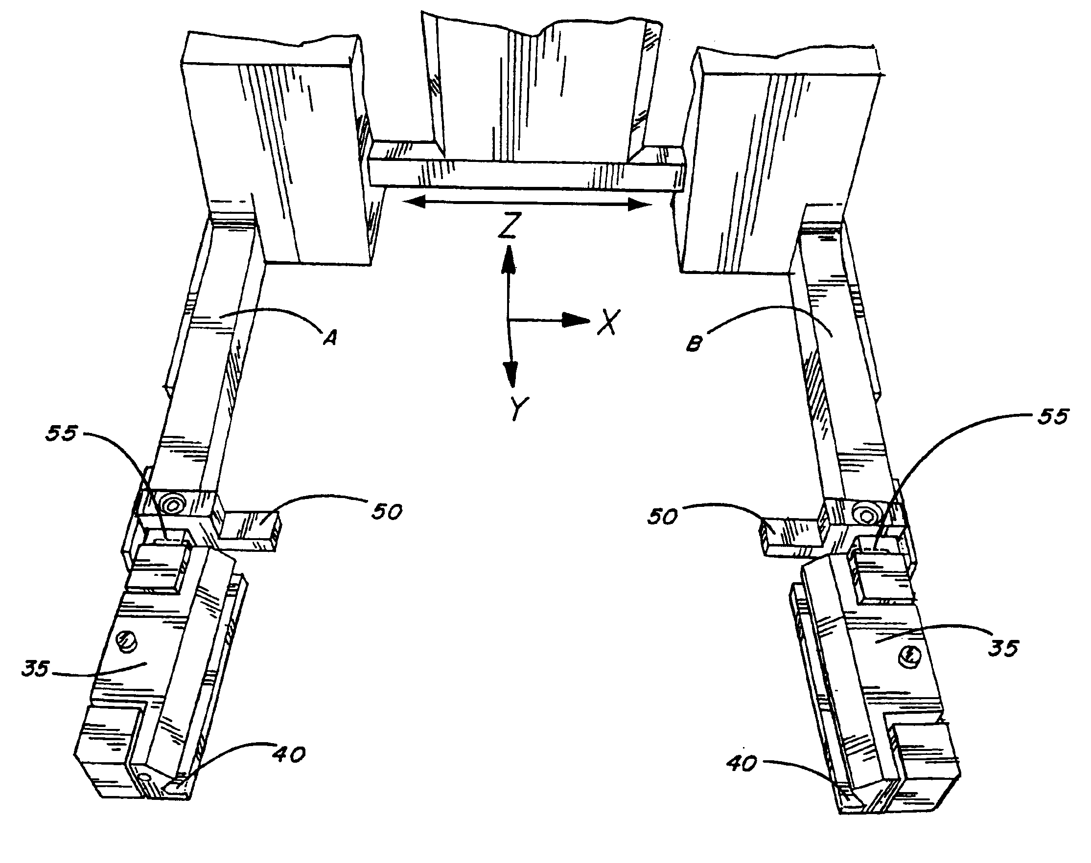
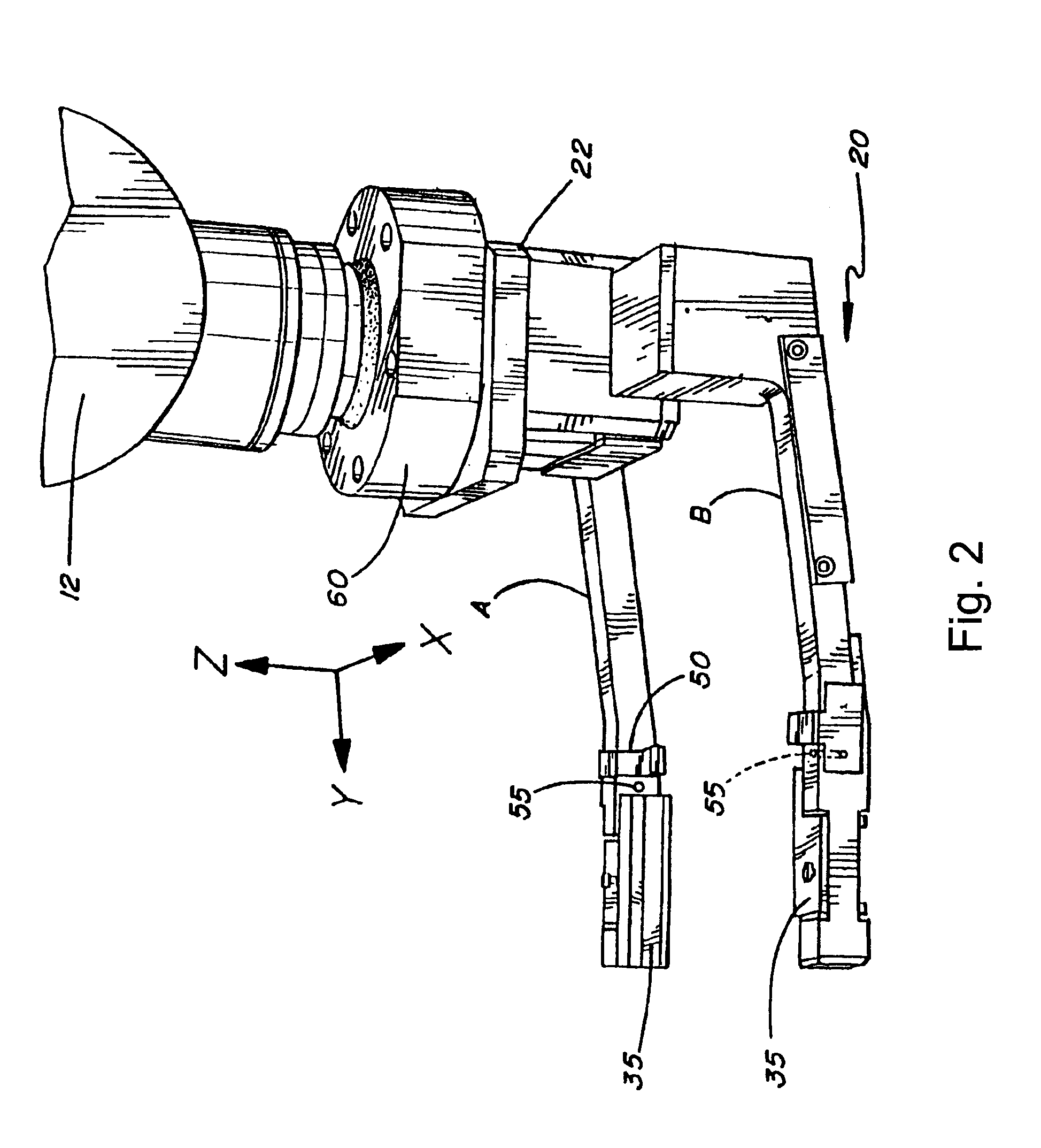
[0009]In particular, the invention includes various related grasping mechanisms. For example, in one aspect the invention provides a grasping mechanism that includes movably coupled arms (e.g., two arms, etc.) in which the arms are movably coupled to each other such that the arms can move towards or away from each other along a first axis (e.g., along an x-axis, etc.). Further, the arms are attached to a body that comprises a resilient coupling which allows the arms to move in a direction substantially perpendicular to the first axis (e.g., along a y-axis, etc.). Although other configurations are optionally utilized (e.g., a grasp that is at least partially internal to an object, etc.), the grasping mechanism is typically structured to grasp the object between the arms. An interface (e.g., a sliding interface, etc.) between the arms and the body typically include at least one spring, which spring resiliently couples the arms to the body. In preferred embodiments, at least one arm includes a stop. In these embodiments, each arm typically includes the stop. Further, the stop is generally structured to determine a y-axis position of the object. In preferred embodiments, the y-axis position of the object is determined with an accuracy to within about 0.1 millimeters. Optionally, the stop includes at least one height adjusting surface and / or at least one support surface. In addition, at least a portion of the grasping mechanism generally includes a polished or coated surface (e.g., coated with TEFLON® or the like) that reduces friction between the object and the grasping mechanism relative to an unpolished or non-coated surface when the object is grasped by the arms. In some embodiments, the arms and / or other grasping mechanism components (e.g., stops, etc.) comprise one or more rollers that reduce friction between the object and the grasping mechanism, relative to arms that lack the rollers, when the object is grasped by the arms.
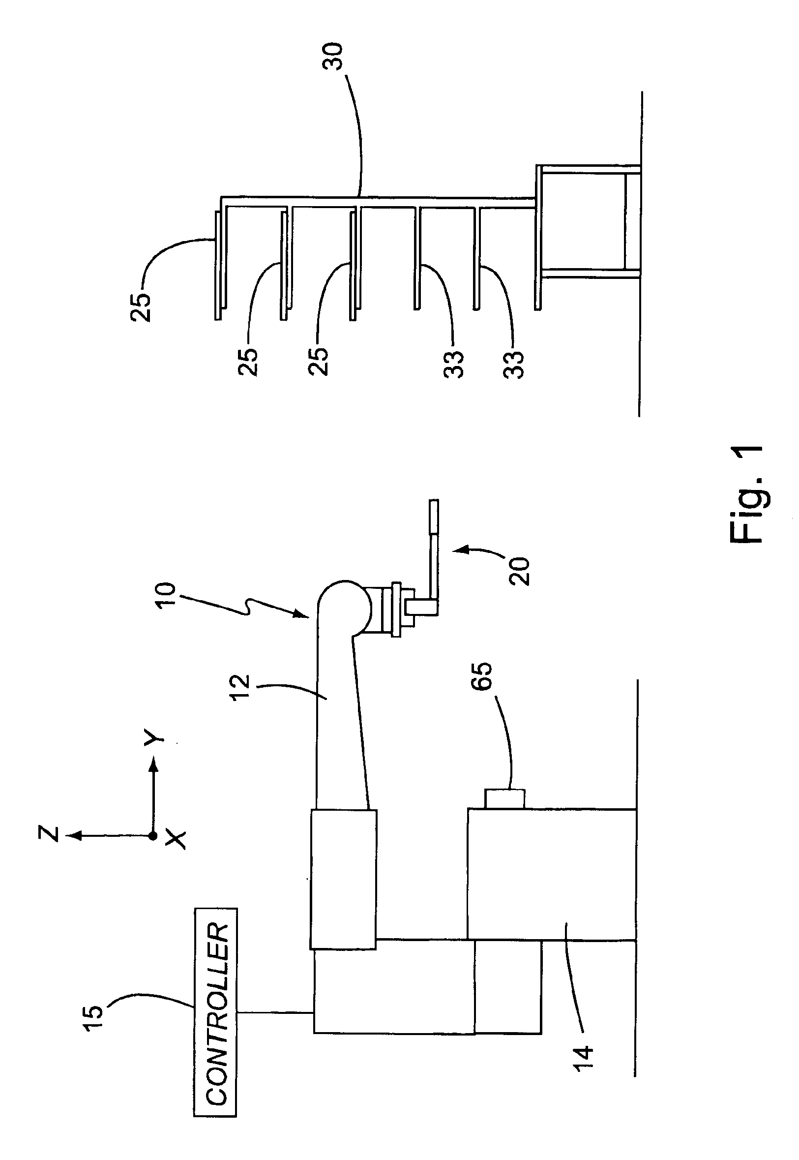
[0014]In another aspect, the invention provides a gripper apparatus that includes a robot that includes a boom. The gripper apparatus also includes a grasping mechanism including movably coupled arms (e.g., two or more arms) that are structured to grasp an object (e.g., between the arms, etc.) in which the grasping mechanism is resiliently coupled to the boom by a resilient coupling. For example, the boom typically moves vertically and horizontally, and optionally further extends and retracts. In addition, the gripper apparatus includes a controller operably connected to at least the grasping mechanism, which controller controls movement of the grasping mechanism. Typically, the controller is operably connected to the robot and further controls movement of the robot. In some embodiments, the resilient coupling (e.g., a sliding interface or the like) between the grasping mechanism and the boom comprises at least one spring, which spring resiliently couples the grasping mechanism to the boom. Typically, at least one, and often each, arm further includes a stop. In these embodiments, the controller generally includes a logic device having one or more logic instructions that direct the gripper apparatus to contact the object such that the object is pushed against a push surface by the stop, whereby the resilient coupling allows the arms to reversibly recede from an initial position, and grasp at least a section of the object with the arms, after which the arms advance at least substantially back to the initial position. Additionally, the logic instructions typically further direct the gripper apparatus to remove the object from a first position and place the object at a second position. In addition, at least a portion of the grasping mechanism generally includes a polished or coated surface (e.g., coated with TEFLON® or the like) that reduces friction between the object and the grasping mechanism relative to an unpolished or non-coated surface when the object is grasped by the arms. Friction is also optionally reduced by incorporating rollers into grasping mechanism surfaces that contact objects.

Problems solved by technology

For example, robots can often perform certain repetitive tasks that generally lead humans to distraction and error.
A positioning error of only a fraction of a millimeter can result in a sample being dispensed into an incorrect well.
Such a mistake can lead to biased assay results which may be relied upon for critical decision making, such as a course of medical treatment for a patient.
In addition, positioning errors can also cause needles or tips of liquid dispensers to unintentionally contact walls or other surfaces of a sample plate with a typical consequence being damage to the liquid dispenser.
Conventional automated or robotic devices typically do not operate with sufficient positioning accuracy, e.g., to reliably and repeatably position high-density sample plates for high-throughput processing.
Additionally, conventional devices also typically require one or more re-gripping steps that further limit throughput.

Method used


Image

  • Gripping mechanisms, apparatus, and methods
  • Gripping mechanisms, apparatus, and methods
  • Gripping mechanisms, apparatus, and methods

Examples


Embodiment Construction

I. Definitions

[0049]Before describing the present invention in detail, it is to be understood that this invention is not limited to particular devices or systems, which can, of course, vary. It is also to be understood that the terminology used herein is for the purpose of describing particular embodiments only, and is not intended to be limiting. Further, unless defined otherwise, all technical and scientific terms used herein have the same meaning as commonly understood by one of ordinary skill in the art to which the invention pertains. In describing and claiming the present invention, the following terminology will be used in accordance with the definitions set out below.

[0050]The term “vertical” refers to a plane that is approximately perpendicular a plane of a horizontal or supporting surface.

[0051]The term “horizontal” refers to a plane that is approximately parallel to a plane of a supporting surface and approximately perpendicular a vertical plane.

[0052]The “x-axis” refers ...


PUM

PropertyMeasurementUnit
rotationaaaaaaaaaa
lengthaaaaaaaaaa
heightaaaaaaaaaa

Abstract

The present invention provides grasping mechanisms, gripper apparatus / systems, and related methods. Grasping mechanisms that include stops, support surfaces, and height adjusting surfaces to determine three translational axis positions of a grasped object are provided. In addition, grasping mechanisms that are resiliently coupled to other gripper apparatus components are also provided.

Description

CROSS-REFERENCES TO RELATED APPLICATIONS[0001]This application is a continuation-in-part of International Patent Application No. PCT / US02 / 06096, entitled “GRIPPER MECHANISMS, APPARATUS, AND METHODS,” which was filed on Feb. 26, 2002 by Downs et al., which is a continuation-in-part of U.S. patent application Ser. No. 09 / 793,254, entitled “GRIPPER MECHANISM,” which was filed on Feb. 26, 2001 now U.S. Pat. No. 6,592,324 by Downs et al.,the disclosures of which are incorporated by reference.COPYRIGHT NOTIFICATION[0002]Pursuant to 37 C.F.R. §1.71(e), Applicants note that a portion of this disclosure contains material which is subject to copyright protection. The copyright owner has no objection to the facsimile reproduction by anyone of the patent document or patent disclosure, as it appears in the Patent and Trademark Office patent file or records, but otherwise reserves all copyright rights whatsoever.FIELD OF THE INVENTION[0003]The present invention relates to gripping devices and met...

Claims


Application Information

Patent Timeline
Patent Type & Authority Patents(United States)
IPC IPC(8): B65G47/90G01N35/04B25J15/02B25J15/08B25J17/02B66C1/00
CPCB25J15/0253B25J17/0208B65G47/90B65H29/02B65H2555/31Y10S294/902Y10S414/141Y10S414/136B65H2555/30
Inventor DOWNS, ROBERT CHARLESWESELAK, MARK RICHARDMAINQUIST, JAMES KEVIN
Owner NOVARTIS AG
Learn More