Single stage, dual channel turbine fuel pump

a dual-channel, single-stage technology, applied in the direction of liquid fuel engines, machines/engines, liquid fuel feeders, etc., can solve the problems of increasing the power consumption rate of multi-stage pumps, and increasing the cost of manufacturing of multi-stage pumps. , to achieve the effect of improving pump efficiency, increasing displacement or output, and reducing cos

Inactive Publication Date: 2005-08-23
TI GRP AUTOMOTIVE SYST LLC
View PDF61 Cites 19 Cited by
  • Summary
  • Abstract
  • Description
  • Claims
  • Application Information

AI Technical Summary

Benefits of technology

[0010]Objects, features and advantages of this invention include providing a turbine fluid pump assembly that has an improved pump efficiency, an increased displacement or output without loss of pumping efficiency or adding of additional components, improved hot fuel performance at high flow rates over a wide pressure range, that does not require adding additional components as with conventional multi-stage designs, has a higher efficiency then conventional single stage and dual stage designs, is easier to manufacture than multi-stage pumps, has a flat performance curve through various pressures and voltages, and where multiple stages can be added without significant cost or complexity, to name but a few. Furthermore, the design is relatively simple and economical to manufacture, and has a significantly increased useful life in service.

Problems solved by technology

Unfortunately, fuel flow cavitation within the pump, especially during hot fuel pumping conditions, continues to be a challenge.
Unfortunately, multi-stage pump designs are expensive to manufacture and have an increased power consumption rate when compared to single stage designs.
Despite the variety of turbine-type pumps and significant improvements in the design and construction of turbine fuel pumps on the market today, they are still somewhat inefficient.
Higher speed results in armature viscous drag (lost efficiency), noise and commutator wear.
However, such alternatives are costly and have an increase in power consumption, thus, which in turn decreases pumping efficiency.

Method used


Image

  • Single stage, dual channel turbine fuel pump
  • Single stage, dual channel turbine fuel pump
  • Single stage, dual channel turbine fuel pump

Examples


Embodiment Construction

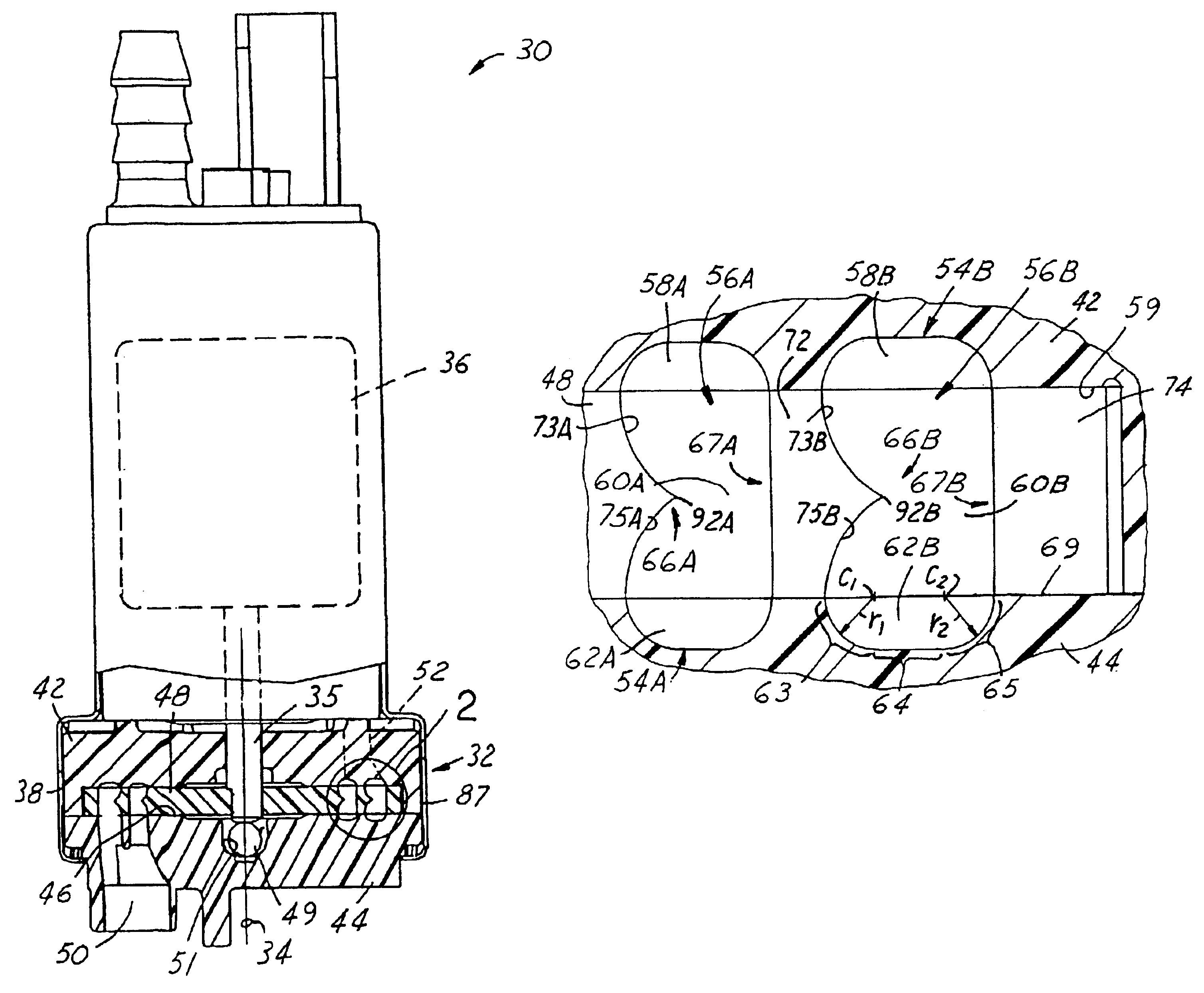
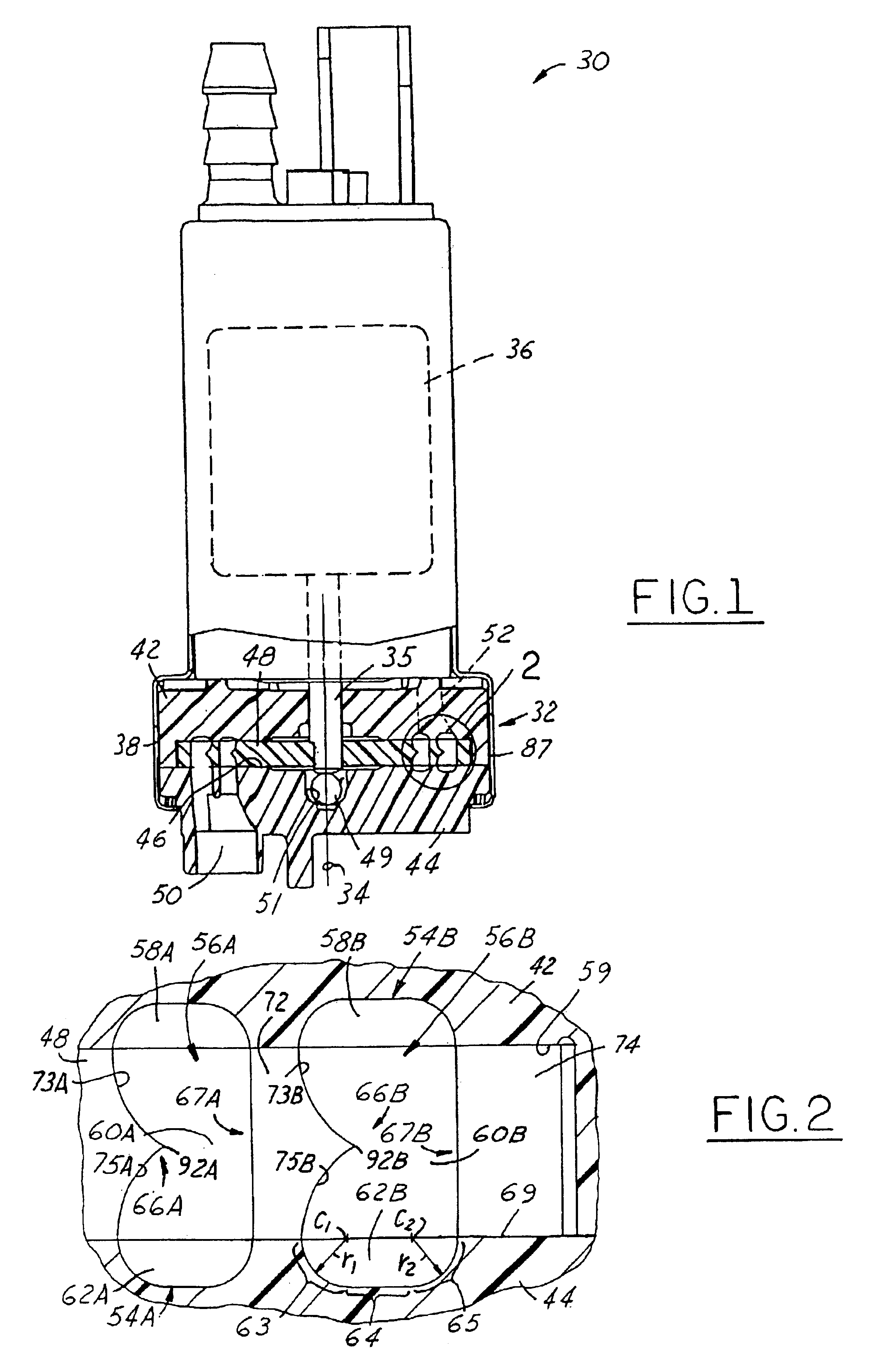
[0034]FIG. 1 illustrates an embodiment of the turbine fuel pump assembly 30 of the present invention, which has a dual side-channel pumping section 32 with an impeller that is preferably powered or rotated on an axis of rotation 34 by an electric motor 36. Pump assembly 30 can be applied to any number of a variety of fluid pumping applications but preferably and for purposes of description, is utilized in an automotive fuel delivery system where the pump assembly is typically mounted in a fuel tank of a vehicle having an internal combustion engine, not shown. An outer housing or sleeve 38 of the pump assembly 30 supports the electric motor 36 and a pumping section 32 in an upright position. In use, typically the axis of rotation 34 extends in a substantially vertical orientation, with respect to the pumping section 32 which is disposed below the motor 36.

[0035]The pumping section 32 includes an upper casing 42 and a lower casing 44, which are held together externally and generally e...


PUM


Abstract

A single stage, dual channel turbine fuel pump for use in a vehicle fuel delivery system, generally including a lower casing, an upper casing, an impeller and a motor. Both the lower and upper casings have a pair of concentric, annular grooves formed on their surfaces, where the two lower annular grooves are in fluid communication with a fuel passage inlet and the two upper annular grooves are in fluid communication with a fuel passage outlet. Rotation of the impeller causes a portion of the incoming fuel to be diverted into an inner lower groove and another portion into an outer lower groove. Once in the lower grooves, the fuel communicates with other parts of the pumping chamber such that it fills the upper grooves as well. Generally independent, helical fuel flow patterns are formed which cause the fuel to become pressurized as it flows from the inlet to the outlet. These helical fuel flow patterns allow for axial communication between vane pockets and corresponding grooves, but do not allow for radial communication.

Description

REFERENCE TO RELATED APPLICATION[0001]Applicant claims the benefit of U.S. Provisional Application No. 60 / 389,676, filed Jun. 18, 2002.TECHNICAL FIELD[0002]This invention relates generally to a turbine fluid pump, and more particularly, to a multi-channel turbine fuel pump for use in a vehicle fuel delivery system.BACKGROUND OF THE INVENTION[0003]Electric motor driven turbine pumps are customarily used in fuel systems of an automotive vehicle and the like. These pumps typically include an external sleeve which surrounds and holds together an internal housing adapted be submerged in a fuel supply tank with an inlet for drawing liquid fuel from the surrounding tank and an outlet for supplying fuel under pressure to an internal combustion engine of the vehicle. A shaft of the electric motor concentrically couples to and drives a pump impeller having an array of circumferentially spaced vanes disposed about the periphery of the impeller. An arcuate pumping channel carried by the housing...

Claims


Application Information

Patent Timeline
Patent Type & Authority Patents(United States)
IPC IPC(8): F04D5/00F02M37/08F04D7/02
CPCF04D5/005
Inventor ROSS, JOSEPH M.
Owner TI GRP AUTOMOTIVE SYST LLC
Why Eureka
Try Eureka