Film cooled article with improved temperature tolerance

a technology of temperature tolerance and cooled components, applied in the field of film cooled articles, can solve the problems of difficult implementation in practice, loss of cooling effect of film, and difficulty in reducing so as to improve the tolerance of elevated temperatures of components, prolong the useful life of cooled components, and sacrifice component durability.

Inactive Publication Date: 2005-08-23
RAYTHEON TECH CORP
View PDF13 Cites 8 Cited by
  • Summary
  • Abstract
  • Description
  • Claims
  • Application Information

AI Technical Summary

Benefits of technology

[0012]11. The principal advantage of the invention is its ability to extend the useful life of a cooled component or to improve the component's tolerance of elevated temperatures without sacrificing component durability. The invention may also make it possible to increase the lateral spacing between discrete film holes, thus economizing on the use of coolant and improving engine performance, without adversely affecting component life. The invention also minimizes the designer's incentive to reduce coolant supply pressure and accept the attendant risk of combustion gas backflow in an effort to promote film adherance.

Problems solved by technology

It is common practice to use multiple, rows of film holes because the coolant film loses effectiveness as it flows along the airfoil surface.
5. Film cooling, despite its merits, can be challenging to execute in practice.
Otherwise the quantity of coolant flowing through the film holes will prove inadequate to satisfactorily film cool the airfoil surfaces.
At worst, the static pressure of the combustion gases may exceed the coolant supply pressure, resulting in ingestion of harmful combustion gases into the plenum by way of the film holes, a phenomenon known as backflow.
The intense heat of the ingested combustion gases can quickly and irreparably damage a blade or vane subjected to backflow.
However, the high coolant pressures required to guard against inadequate coolant flow and backflow can cause the coolant jets to penetrate into the flowpath rather than adhere to the surface of the airfoil.
Thus, the high pressure coolant jets not only leave part the airfoil surface exposed, but actually entrain the hot, damaging gases into the exposed zone.
In addition, the cohesiveness of the jets impedes their ability to spread out laterally (i.e. in the spanwise direction) and coalesce into a spanwisely continuous film.
Unfortunately, installing shallow angle film holes is both expensive and time consuming.
Moreover, such holes contribute little or nothing to the ability of the coolant to spread out laterally and coalesce into a continuous film.
Although shaped holes can be beneficial, they are difficult and costly to produce.

Method used


Image

  • Film cooled article with improved temperature tolerance
  • Film cooled article with improved temperature tolerance
  • Film cooled article with improved temperature tolerance

Examples


Embodiment Construction

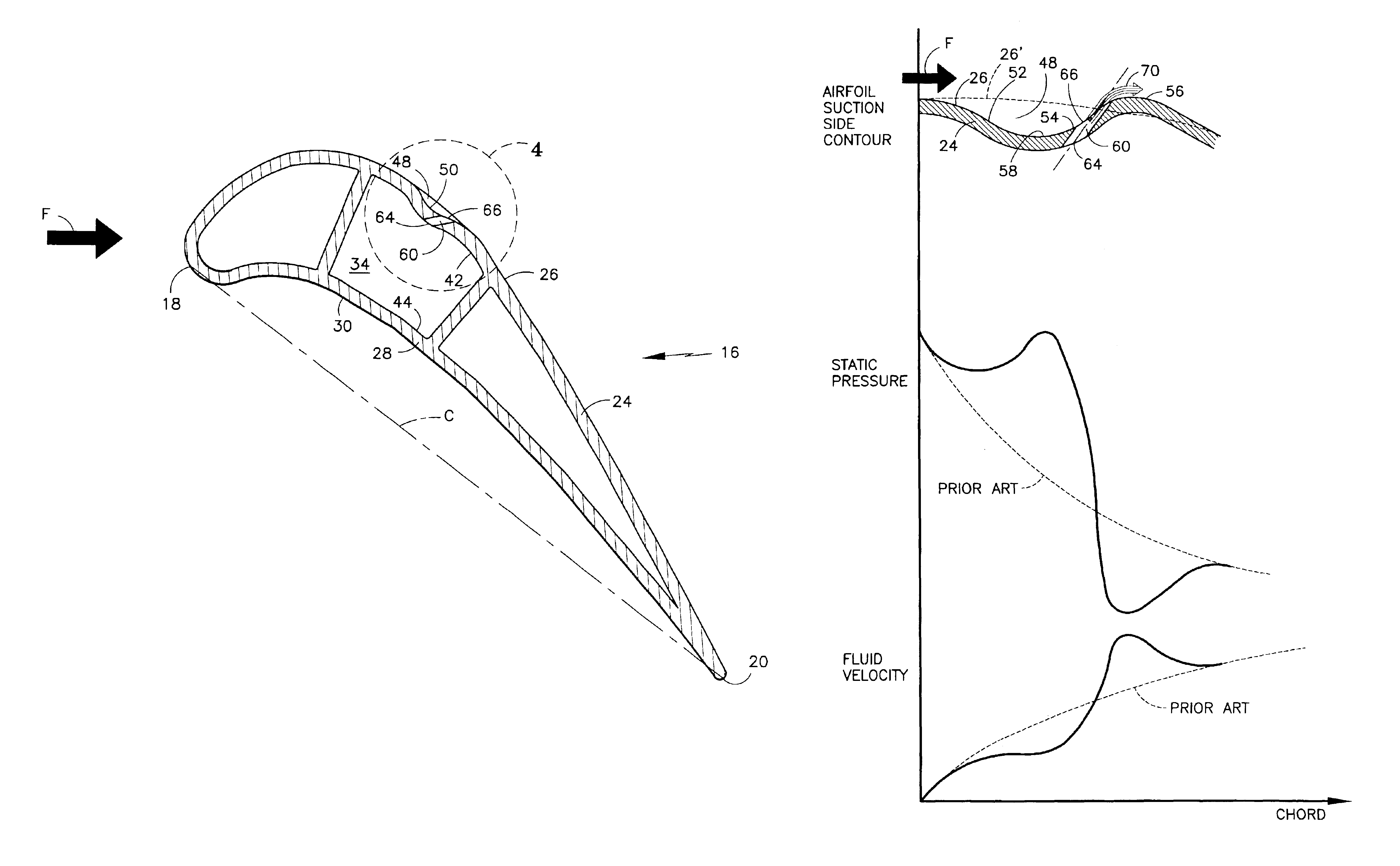
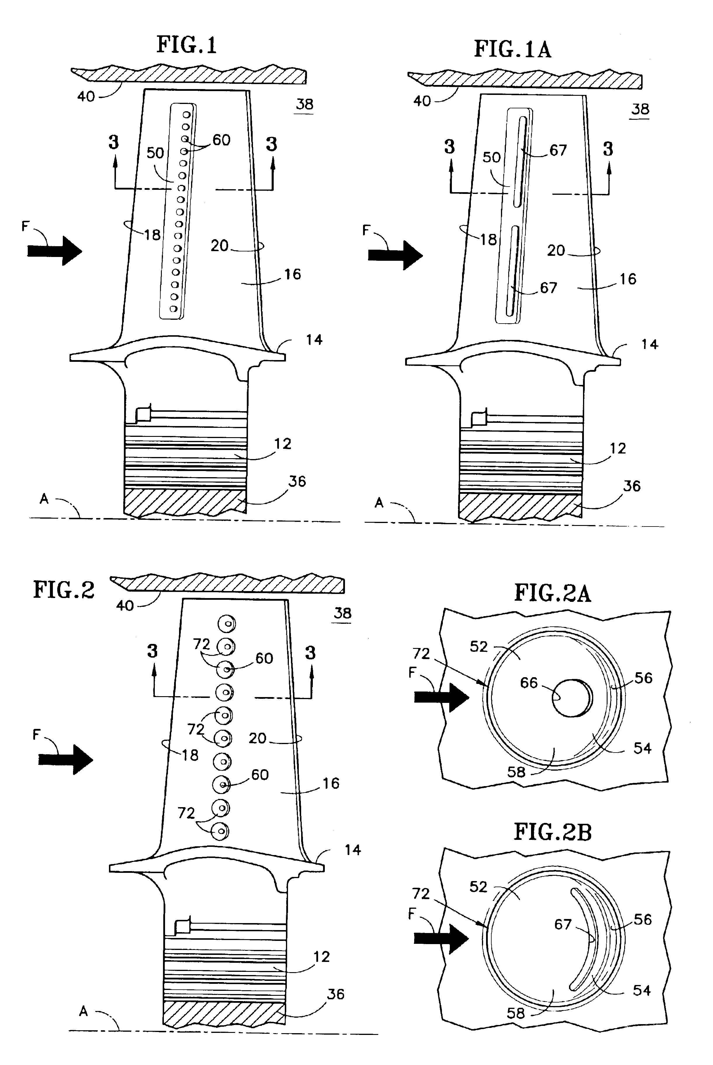
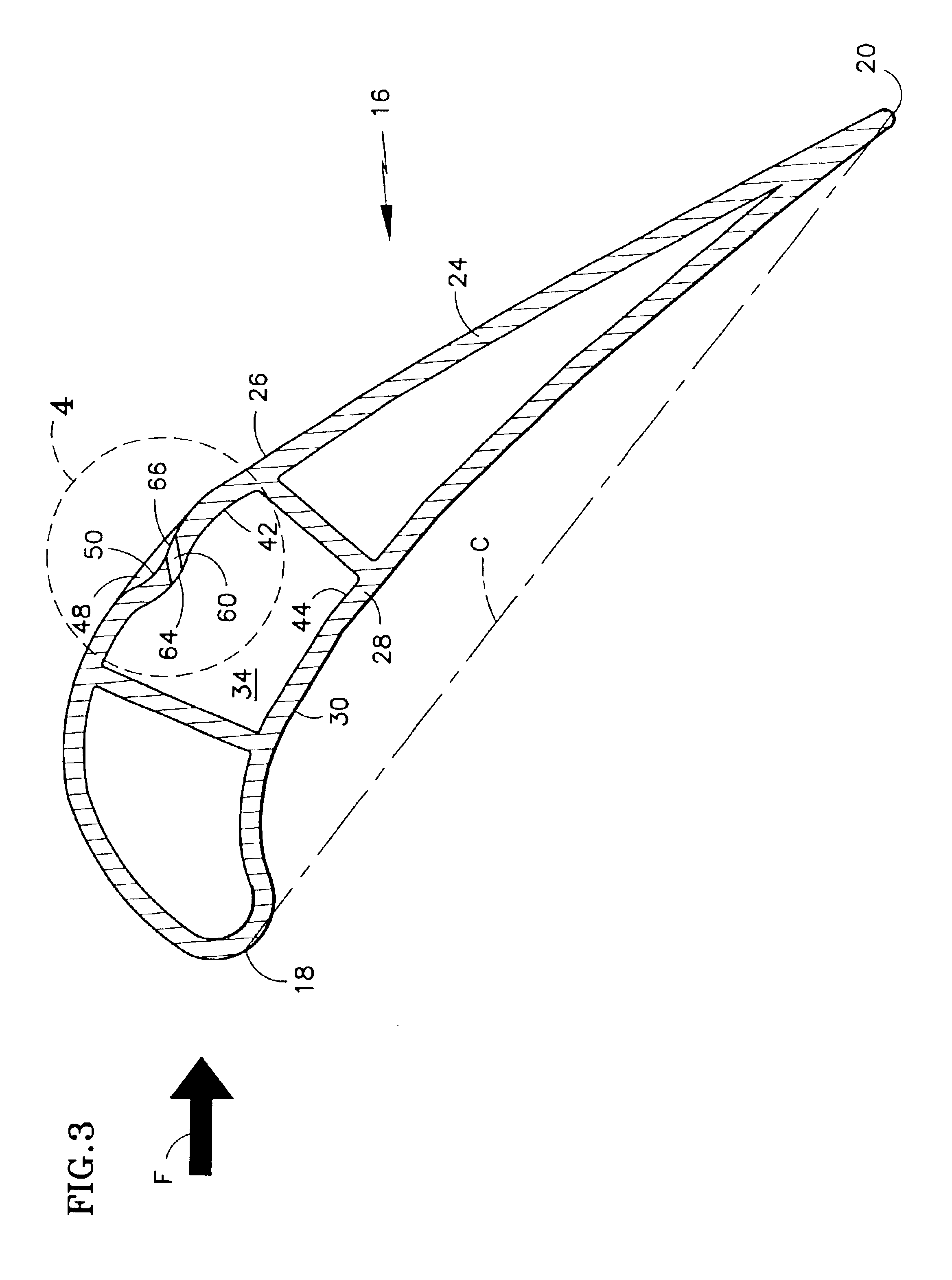
[0022]21. FIGS. 1 and 3 illustrate a turbine blade for the turbine module of a gas turbine engine. The blade includes a root 12, a platform 14 and airfoil 16. The airfoil has a leading edge 18, defined by an aerodynamic stagnation point, a trailing edge 20, and a notional chord line C extending between the leading and trailing edges. The airfoil has a wall comprised of a suction wall 24 having a suction surface 26, and a pressure wall 28 having a pressure surface 30. Both the suction and pressure walls extend chordwisely from the leading edge to the trailing edge. One or more internal plenums, such as representative plenum 34, receive coolant from a coolant source, not shown. In a fully assembled turbine module, a plurality of circumferentially distributed blades radiates from a rotatable hub 36, with each blade root being captured in a corresponding slot in the periphery of the hub. The blade platforms collectively define the radially inner boundary of an annular fluid flowpath 38....


PUM


Abstract

The invention is a film cooled article such as a turbine engine blade or vane, having a wall with a hot surface 26 to be film cooled. The hot surface 26 includes a depression 48 featuring a descending flank 52 and an ascending flank 54. Coolant holes 60, which penetrate through the wall, have discharge openings residing on the ascending flank 54. During operation, the depression locally over-accelerates a primary fluid stream F flowing over the ascending flank while coolant jets 70 concurrently issue from the discharge openings. The local over-acceleration of the primary fluid deflects the jets onto the hot surface and spatially constrains the jets thus encouraging them to spread out laterally and coalesce into a laterally continuous, protective coolant film. In one embodiment, the depression 48 is a trough 50. In another embodiment, the depression is a dimple 72.

Description

[0001]This is a continuation of application Ser. No. 09 / 861,753 filed on May 21, 2001 now U.S. Pat. No. 6,547,524.STATEMENT OF GOVERNMENT INTEREST[0002]1. This invention was made under a U.S. Government Contract and the Government has rights herein.TECHNICAL FIELD[0003]2. This invention pertains to film cooled articles, such as the blades and vanes used in gas turbine engines, and particularly to a blade or vane configured to promote superior surface adherence and lateral distribution of the cooling film.BACKGROUND OF THE INVENTION[0004]3. Gas turbine engines include one or more turbines for extracting energy from a stream of hot combustion gases that flow through an annular turbine flowpath. A typical turbine includes at least one stage of blades and one stage of vanes streamwisely spaced from the blades. Each stage of blades comprises multiple, circumferentially distributed blades, each radiating from a rotatable hub so that an airfoil portion of each blade spans across the flowpa...

Claims


Application Information

Patent Timeline
Patent Type & Authority Patents(United States)
IPC IPC(8): F01D5/18F01D5/14F01D9/02
CPCF01D5/141F01D5/186
Inventor KOHLI, ATULWAGNER, JOEL H.AGGARWALA, ANDREW S.
Owner RAYTHEON TECH CORP
Why Eureka
Try Eureka