
Ceiling and floor mounted surgical robot set-up arms

a surgical robot and floor-mounted technology, applied in the field of surgical devices, systems and methods, can solve the problems of occupying significant volume, requiring space to have range of motion, and occupying the setup arms of the telesurgical arm, and achieve the effect of optimizing space utilization

Inactive Publication Date: 2005-08-23
INTUITIVE SURGICAL OPERATIONS INC
View PDF34 Cites 129 Cited by
  • Summary
  • Abstract
  • Description
  • Claims
  • Application Information

AI Technical Summary

Benefits of technology

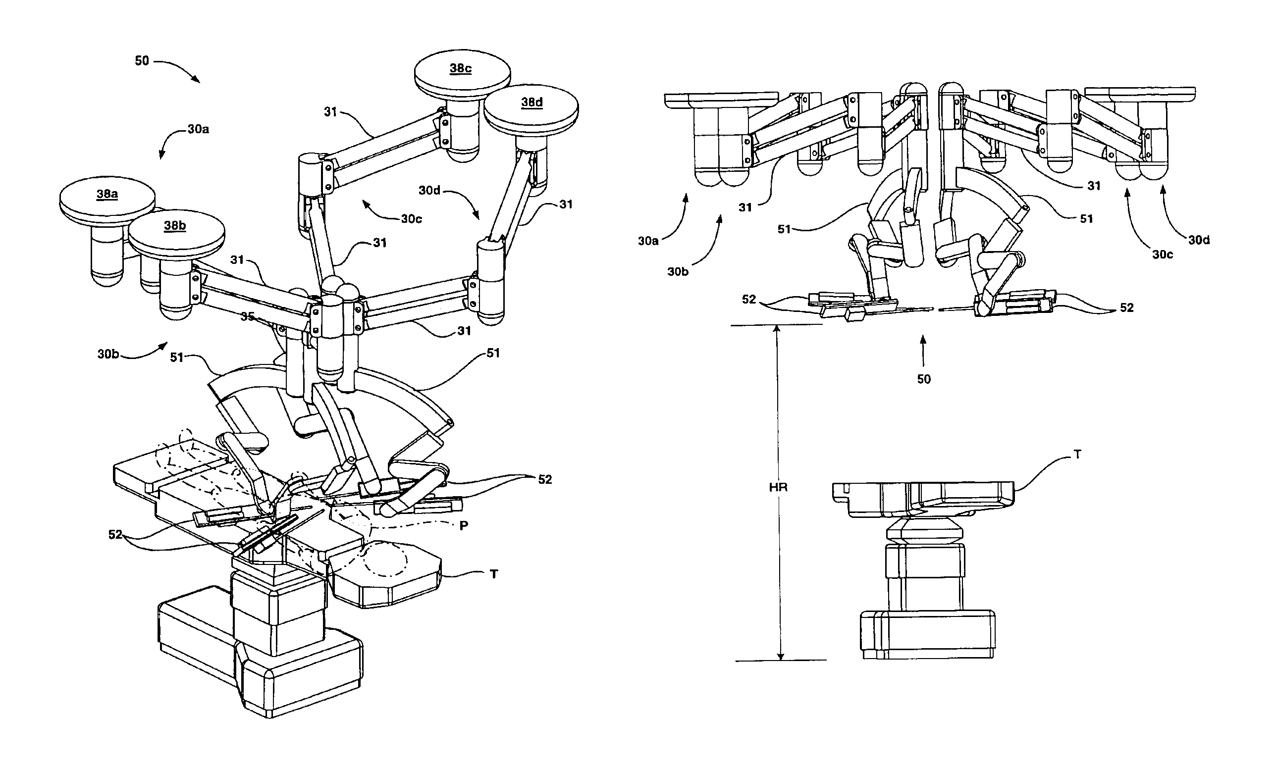
The present invention provides improved methods and mechanisms for configuring and arranging the setup arms of surgical manipulators and endoscope drive mechanisms in telesurgical systems. The invention aims to optimize space utilization in the operating room and allow for cooperative operation by two surgeons. The invention also minimizes the intrusion of the setup arms into the personnel-usable space and avoids collisions with other surgical equipment. The setup arms are pre-configurable or manually positionable to allow for three-dimensional manipulation of surgical instruments and orientation of the surgical instrument by rotating the manipulator and instrument about one, two, or three axes of rotation. The linkages are lockable joints to maintain a fixed configuration and can be manually moved by operating room personnel. The invention also provides position tracking sensors or encoders to measure the motion, position, and angles of the linkage elements and joints. Overall, the invention improves the efficiency and effectiveness of telesurgical systems in the operating room.

Problems solved by technology

The telesurgical setup arms, and their respective PSM or ECM, occupy significant volume and require space to have range of motion for positioning.
In addition, the environment of an operating room is often crowded with competing demands for space needed for an anesthesiologist, related equipment, surgeon's assistants, life support equipment, lights, surgical tool storage, instrumentation, displays, and the like.

Method used


Image

  • Ceiling and floor mounted surgical robot set-up arms
  • Ceiling and floor mounted surgical robot set-up arms
  • Ceiling and floor mounted surgical robot set-up arms

Examples


Embodiment Construction

[0046]The following detailed description illustrates the invention by way of example, not by way of limitation of the principles of the invention. All publications and patent applications cited in this specification are herein incorporated by reference as if each individual publication or patent application were specifically and individually indicated to be incorporated by reference and the full disclosure of each was set forth herein.

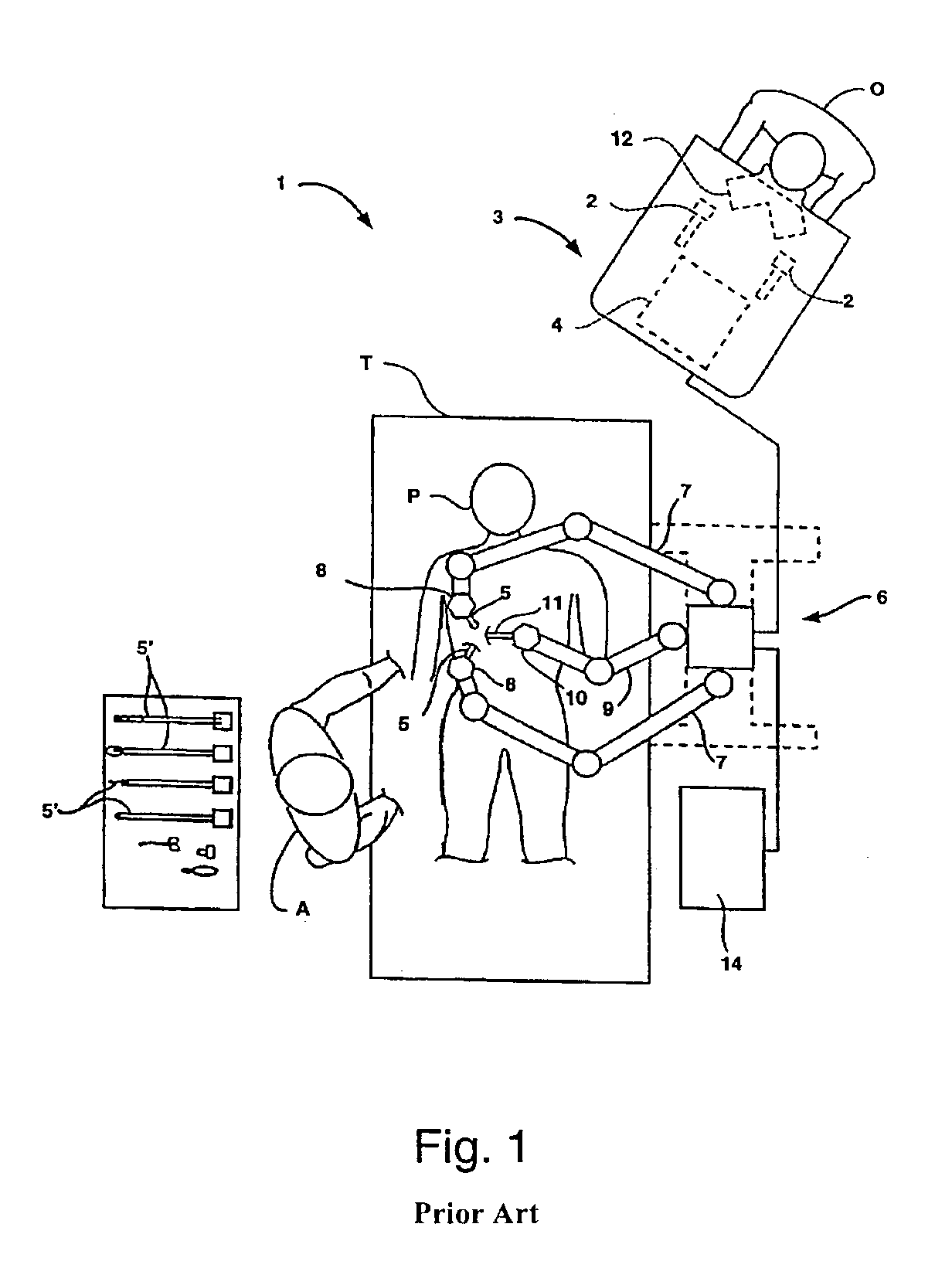
[0047]FIG. 1 is a schematic plane view of a portion of an operating room showing by way of background an exemplary robotic surgical system 1 performing a minimally invasive robotic surgical procedure, such as described in WO00 / 07503. An operator O (generally a surgeon) performs a minimally invasive surgical procedure on patient P lying on operating table T, the operator O manipulating one or more input devices or masters 2 at a surgeon's console 3. In response to the surgeon's inputs, a computer processor 4 of console 3 directs movement of endoscopic s...


PUM


Abstract

The present invention generally relates to surgical devices, systems, and methods, especially for minimally invasive surgery, and more particularly provides structures and techniques for aligning a robotic surgery system with a desired surgical site. The present invention describes techniques for mounting, configuring and arranging set-up arms for the surgical manipulators and endoscope drive mechanisms of a telesurgical system within an operating theater. The various aspects of the invention improve and optimize space utilization in the conduct of a surgical procedure, especially in the telesurgical systems which provide for concurrent operation by two surgeons using multiple robotic arm assemblies. In one aspect, the invention includes a method and apparatus for ceiling-height mounting of surgical set-up arms, and in another aspect, the invention includes a method and apparatus for the mounting of surgical setup arms to the table pedestal or floor below an operating table. The ceiling-height-mounted robotic arm assembly and below-table-mounted robotic arm assembly may be pre-configured to be ready for surgery while the fixable set-up arms are disposed generally clear of the personnel-usable space adjacent the operating table. Examples are described of separate and combined use of the ceiling mount and floor / pedestal mount aspects in both single and dual surgeon telesurgical systems.

Description

CROSS-REFERENCES TO RELATED APPLICATIONS[0001]This application is a Continuation of U.S. patent application Ser. No. 10 / 028,999, filed Dec. 20, 2001, now U.S. Pat. No. 6,788,018, which claims benefit of Provisional Patent Application No. 60 / 258,058, filed Dec. 22, 2000, and which is also a Continuation-in-Part of and claims the benefit of priority from U.S. patent application Ser. No. 09 / 368,309, filed Aug. 3, 1999, now U.S. Pat. No.6,246,200, entitled “Manipulator Positioning Linkage For Robotic Surgery”; which was the basis for International Application No. PCT / US99 / 17522, filed Aug. 3, 1999, published on Feb. 17, 2000 as WO00 / 07503.[0002]The present application is also related to the following commonly owned patent applications:[0003]Ser. No. 09 / 433,120, filed on Nov. 3, 1999, now U.S. Pat. No. 6,659,939 entitled “Cooperative Minimally Invasive Telesurgical System”, which was the basis for International Application No. PCT / US99 / 27619, filed Nov. 18, 1999 and published as WO00 / 305...

Claims


Application Information

Patent Timeline
Patent Type & Authority Patents(United States)
IPC IPC(8): A61B19/00B25J9/10
CPCA61B19/22A61B19/2203B25J9/0018B25J9/1065A61B2019/2223A61B2019/263A61B2019/264A61B2019/265A61B2017/00477Y10S128/07A61B2090/5025A61B2090/504A61B2090/506A61B34/70A61B34/30A61B34/37
Inventor BLUMENKRANZ, STEPHEN J.
Owner INTUITIVE SURGICAL OPERATIONS INC
Learn More