Variable gain low noise amplifier

a low-noise amplifier, variable-gain technology, applied in the direction of low-noise amplifiers, gated amplifiers, gain control, etc., can solve the problems of low gain, low noise characteristics of high-gain states, poor matching, etc., and achieve the effect of reducing the capability of low-noise amplifiers

Inactive Publication Date: 2005-08-23
INTEGRANT TECH
View PDF3 Cites 42 Cited by
  • Summary
  • Abstract
  • Description
  • Claims
  • Application Information

AI Technical Summary

Benefits of technology

[0013]The object of the present invention is to provide a variable gain low noise amplifier in which the circuits are designed to operate in the best suited way such that each gain mode does not affect the capability of the best suited circuit to operate in the other gain mode.
[0014]Another object of the present invention is to provide a variable gain low noise amplifier for which input matching, gain, noise characteristics, linearity, etc. can display the capability of the best suited circuit in different modes.
[0016]Another object of the present invention is to provide a variable gain low noise amplifier whose power consumption is low.

Problems solved by technology

As a result, the gain, matching, and noise characteristics of the high gain state are not good, and the capability of the low noise amplifier is reduced.

Method used


Image

  • Variable gain low noise amplifier
  • Variable gain low noise amplifier
  • Variable gain low noise amplifier

Examples


Embodiment Construction

[0034]Hereinafter, preferred embodiments of the present invention will be described in detail with reference to the attached drawings.

[0035]Here, a common source and gate low noise amplifier of the prior art will be described, and then proper embodiments of a variable gain low noise amplifier according to present invention will be described in detail with reference to the attached drawings.

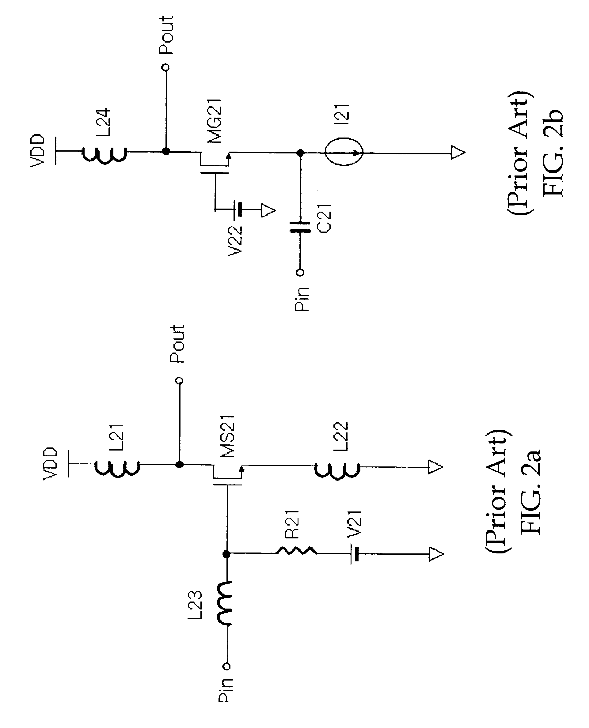
[0036]FIG. 2a shows a common source amplifier of the prior art.

[0037]Referring to FIG. 2a, a common source amplifier comprises an NMOS transistor MS21, first inductor L21, second inductor L22 and third inductor L23, resistor R21 and voltage source V21. The drain of the NMOS transistor MS21 is formed to connect to an output terminal Pout connected with one of terminals of first inductor L21, the gate is connected with the resistor R21 and third inductor L23, and the source is connected with one of the terminals of the second inductor L22. The other terminal of the first inductor L21 is connected to...


PUM


Abstract

The present invention is related to a variable gain low noise amplifier that optimizes input matching, gain and noise characteristics, and linearity. The variable gain low noise amplifier according to an embodiment of the present invention includes a first amplifying cell that operates in a high gain mode, a second amplifying cell that operates in a low gain mode, a selectively matching circuit, and a first short-circuit means. The variable gain low noise amplifier according to the present invention selects the best operation in each gain mode so that the circuit operated in high and low gain modes does not affect a load of another circuit.

Description

TECHNICAL FIELD[0001]The present invention relates to a Low Noise Amplifier (hereinafter referred to as an “LNA”), more specifically, it is related to a variable gain LNA that is operated most suitably in input matching, gain and noise characteristics, linearity, etc.BACKGROUND OF THE INVENTION[0002]A first terminal is comprised of an amplifier that generally amplifies small signals to large signals in wireless equipment, for example a portable phone, TV, etc. This amplifier is made to have an amplifying operation having low noise and high gain characteristics when the signal is very small. But linearity is demanded rather than the amplifying operation when the signal is relatively large. Therefore, the amplifier satisfies more than two kinds of amplifying modes according to the input signal level, and it is necessary that the amplifier selects one of them in the wireless frequency receiving equipment.[0003]As a low noise amplifier of the prior art, it is disclosed in U.S. Pat. No 6...

Claims


Application Information

Patent Timeline
Patent Type & Authority Patents(United States)
IPC IPC(8): H03G1/00H03F3/72H03F1/26
CPCH03F3/72H03G1/0088H03F2200/294H03F2200/372H03F2203/7236H03F1/26
Inventor LEE, KWYROKIM, TAE WOOK
Owner INTEGRANT TECH
Why Eureka
Try Eureka