

Method of controlling intermodulation distortion of non-reciprocal device
a non-reciprocal device and intermodulation distortion technology, applied in waveguide devices, magnetic materials, magnetic bodies, etc., can solve the problems of crosstalk or noise, degrading the performance and preventing the application of a sufficient d.c. magnetic field to the ferrimagnetic member, so as to achieve the effect of improving the intermodulation distortion of the non-reciprocal devi
- Summary
- Abstract
- Description
- Claims
- Application Information
AI Technical Summary
Benefits of technology
Problems solved by technology
Method used
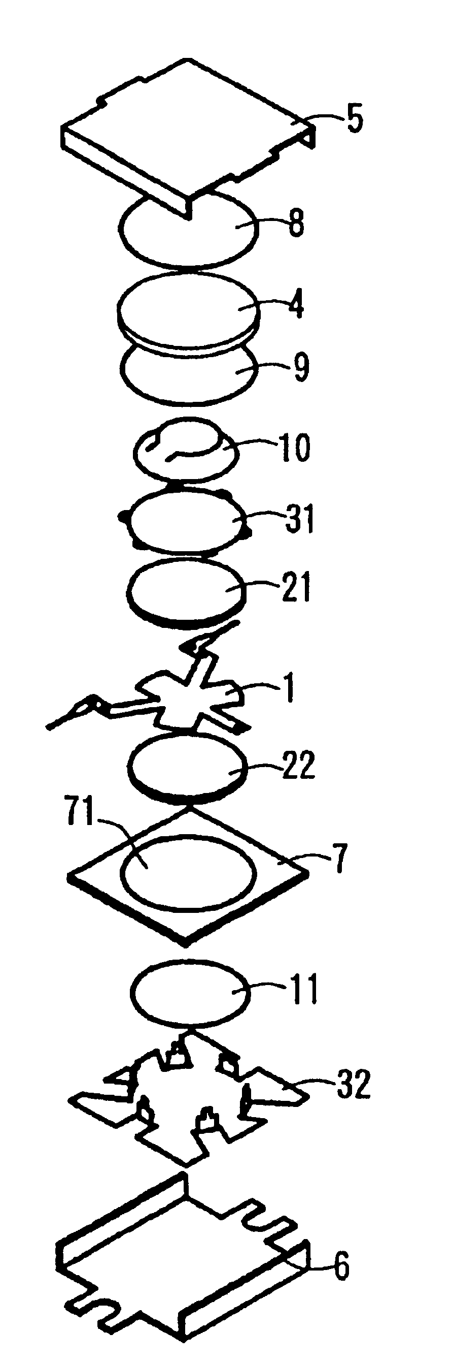
Image

Examples
example 1
[0066]After having been sintered raw materials Y2O3, CaCO3, Fe2O3, ZrO2, V2O5, and Al(OH)3 were weighed so as to assume a target composition (Y3−2x−z+wCa2X+Z)(Fe5−x−y−z−wVxAlyZrz)O12. After having been wet-mixed by means of a ball mill for 20 hours, the materials were calcined at 1100 to 1200° C. for four (4) hours in the air. The thus-calcined materials were transferred to the ball mill and subjected to compression molding after having been subjected to wet grinding for 20 hours. The optimum temperature of the thus-obtained mold was selected from the range of 1250 to 1450° C. such that the FMR linewidth ΔH of the composition was minimized and a particle size of 15 μm or more was obtained. The mold was sintered for six (6) hours in oxygen. X-ray diffraction of the thus-obtained sintered compact (sintered material) indicates that the sintered compact has a garnet single phase.
[0067]Here, according to the Bond Method, a ball sample having a diameter of 1.0 mm (SAMPLE) was formed from ...
example 2
[0075]Regarding the sintered compact having a saturation magnetic flux density 4πMs of 1750 Gauss or thereabouts, the SAMPLE was made in the same manner as in Example 1. The characteristics of the SAMPLE were determined, and results are shown in Table 3. In Table 3, Material No. 21 designates a ‘conventional’ yttrium-iron garnet ferrite, which is non-substituted by Zr, (hereinafter called and also represented as ‘Y—Fe garnet ferrite’), and Material Nos. 22 through 26 designate materials employed in Example 2.
[0076]With regard to the FMR linewidth ΔH, which is relevant to an IMD, that of Material No. 21 assumes a value of 25[Oe], in contrast, that of each of Material Nos. 22 through 26 assumes a value smaller than 15[Oe]. Accordingly, as compared with conventional Material No. 21, all Material Nos. 22 through 26 are improved in terms of an IMD.
[0077]With regard to the curie temperature, that of Material No. 21 assumes a value of 275° C., in contrast, that of each of Material Nos. 22 ...
example 3
[0083]Regarding the sintered compact having a saturation magnetic flux density 4ρMs of 750 Gauss or thereabouts, the SAMPLE was made in the same manner as in Example 1. The characteristics of the SAMPLE were determined, and the results are shown in Table 4. Material No. 0.31 designates a conventional Y—Al—Fe garnet ferrite, which is a sample formed from material having a saturation magnetic flux density 4πMs of 750 Gauss. Material Nos. 32 through 43 are samples formed from materials having saturation magnetic flux densities 4πMs from 740 to 780 Gauss.
[0084]With regard to the FMR linewidth ΔH which is relevant to an IMD, that of Material No. 31 assumes a value of 30[Oe], in contrast, that of Material No. 33 and that of each of Material Nos. 38 through 43 assume a value smaller than 15[Oe].
[0085]With regard to the curie temperature Tc, that of Material No. 31 assumes a value of 175° C.; that of Material No. 34 assumes a value of 179° C.; and that each of Material Nos. 40 through 42 as...
PUM
| Property | Measurement | Unit |
|---|---|---|
| Auxiliary magnetic field | aaaaa | aaaaa |
| Ferrimagnetism | aaaaa | aaaaa |
| Magnetic flux density | aaaaa | aaaaa |
Abstract
Description
Claims
Application Information