
Electro-ferromagnetic, tunable electromagnetic band-gap, and bi-anisotropic composite media using wire configurations

a technology of bianisotropic composite media and wire configuration, which is applied in the direction of resonators, waveguides, antennas, etc., can solve the problem that the medium is incapable of supporting propagating waves, and achieve the effect of increasing the bandwidth of the stop band, increasing the effective dielectric of the background material, and reducing the size of the /4 section

Inactive Publication Date: 2005-08-23
RGT UNIV OF MICHIGAN
View PDF6 Cites 80 Cited by
  • Summary
  • Abstract
  • Description
  • Claims
  • Application Information

AI Technical Summary

Benefits of technology

The present invention presents a new method for designing miniaturized tunable electromagnetic band-gap meta-materials that offer novel electromagnetic material functionalities. These meta-materials can be tailored to have desired characteristics, including tunable permeability, electromagnetic band-gap, and bi-anisotropic properties. The invention uses a periodic structure of embedded resonant circuits to generate a μ material, which is simpler to fabricate than previous methods. The effective medium parameters of the proposed meta-materials can be designed using analytical formulations and verified using a powerful FDTD full-wave technique. The invention offers new functionalities and can be used to design miniaturized antennas and RF circuits.

Problems solved by technology

For a material with negative εeff or μeff the propagation constant becomes purely imaginary, meaning that the medium is incapable of supporting propagating waves.

Method used


Image

  • Electro-ferromagnetic, tunable electromagnetic band-gap, and bi-anisotropic composite media using wire configurations
  • Electro-ferromagnetic, tunable electromagnetic band-gap, and bi-anisotropic composite media using wire configurations
  • Electro-ferromagnetic, tunable electromagnetic band-gap, and bi-anisotropic composite media using wire configurations

Examples


Embodiment Construction

Embedded-Circuit Meta-Materials

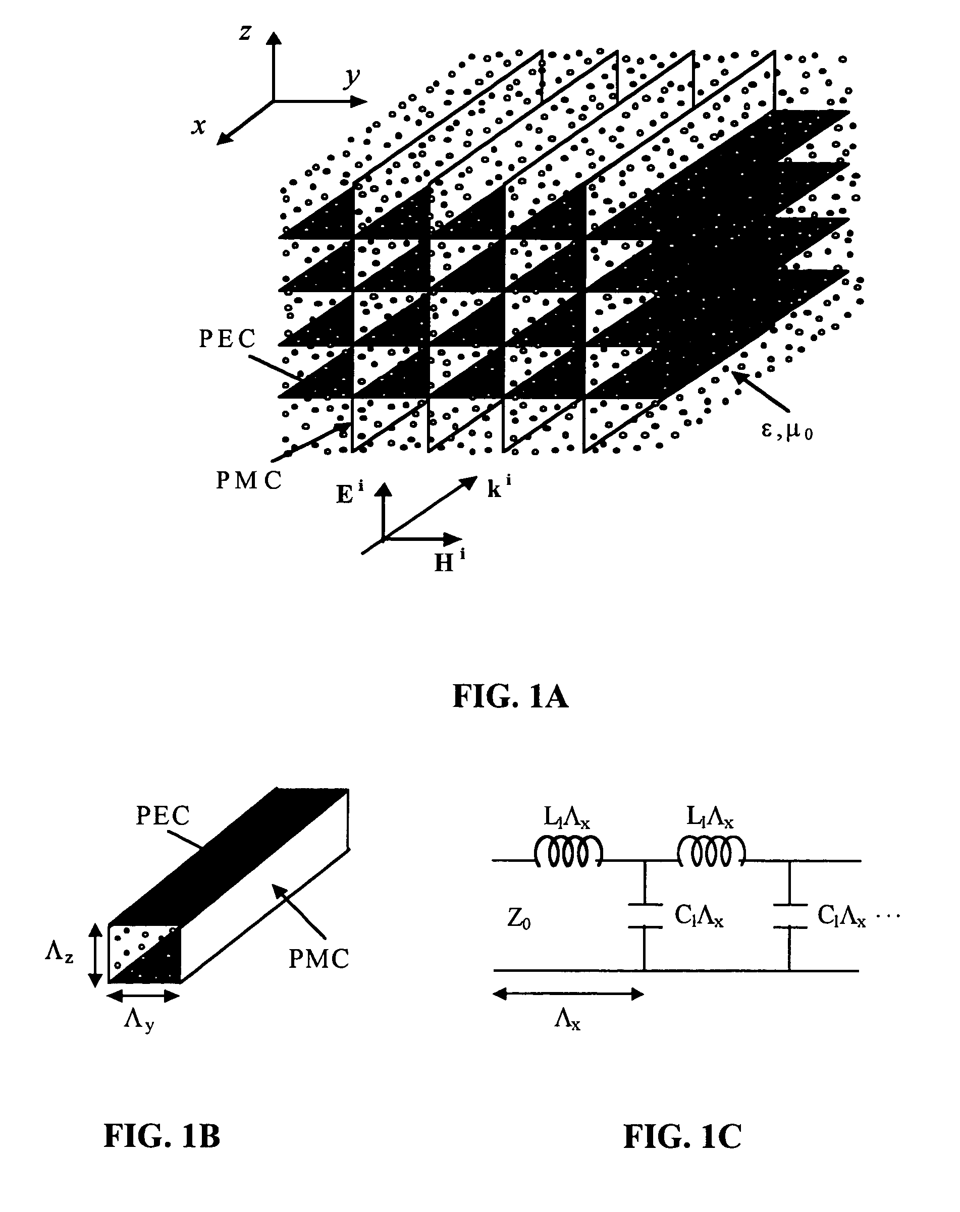
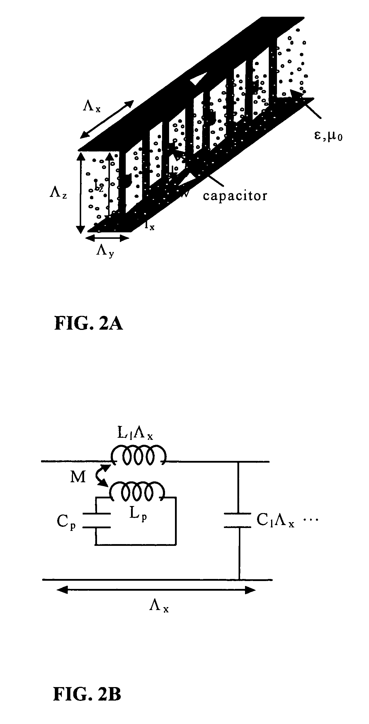
[0043]In this section the main concept of embedded-circuit meta-materials is introduced and an analytical approach for characterizing their macroscopic material property is presented. The analytical technique is based on a transmission line method that account for mutual interaction of all embedded-circuits. The FDTD numerical technique is also applied to validate the results.

Transmission Line Method

[0044]The simplest form of electromagnetic waves in a homogeneous and source free region is a transverse electromagnetic (TEM) plane wave. Basically a plane wave is an eigenfunction of the wave equation whose corresponding eigenvalue, the propagation constant κ, is a function of the medium constitutive parameters. The interest in studying the behavior of plane waves in a medium stems from the fact that any arbitrary wave function can be expressed in terms of a superposition of these fundamental wave functions. For a simple medium, the permittivity and perme...


PUM


Abstract

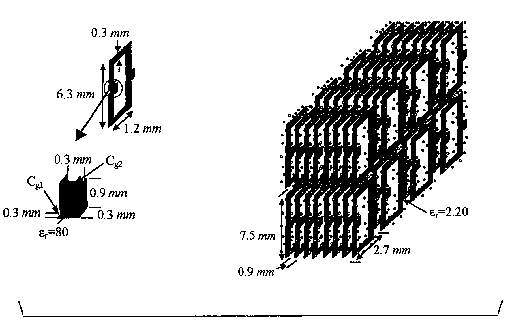
An artificial electro-ferromagnetic meta-material demonstrates the design of tunable band-gap and tunable bi-anisotropic materials. The medium is obtained using a composite mixture of dielectric, ferro-electric, and metallic materials arranged in a periodic fashion. By changing the intensity of an applied DC field the permeability of the artificial electro-ferromagnetic can be properly varied over a particular range of frequency. The structure shows excellent Electromagnetic Band-Gap (EBG) behavior with a band-gap frequency that can be tuned by changing the applied DC field intensity. The building block of the electro-ferromagnetic material is composed of miniaturized high Q resonant circuits embedded in a low-loss dielectric background. The resonant circuits are constructed from metallic loops terminated with a printed capacitor loaded with a ferro-electric material. Modifying the topology of the embedded-circuit, a bi-anisotropic material (tunable) is examined. The embedded-circuit meta-material is treated theoretically using a transmission line analogy of a medium supporting TEM waves.

Description

RELATED APPLICATIONS[0001]This application claims the benefit of provisional application Ser. No. 60 / 417,435 filed on Oct. 10, 2002 and incorporates that application in its entirety by reference.STATEMENT REGARDING FEDERALLY SPONSORED RESEARCH OR DEVELOPMENT[0002]The U.S. Government has a paid-up license in this invention and the right in limited circumstances to require the patent owner to license others on reasonable terms as provided for by Grant No. DARPA N000173-01-1G910.FIELD OF THE INVENTION[0003]The focus in the present invention is to investigate the unique properties of a novel tunable periodic structure composed of conducting wire loops printed on dielectric material and the proposed structure has the potential to be integrated in introducing three unique structures, namely, electro-ferromagnetic structures, band-gap materials, and bi-anisotropic media.BACKGROUND OF THE INVENTION[0004]In a sense, every material can be considered as a composite, even if the individual ingr...

Claims


Application Information

Patent Timeline
Patent Type & Authority Patents(United States)
IPC IPC(8): H01P7/00H01P3/08H01Q1/38H01Q15/00
CPCH01P1/2005H01P3/08H01Q1/38H01Q15/006H01Q15/0086
Inventor SARABANDI, KAMALMOSALLAEI, HOSSEIN
Owner RGT UNIV OF MICHIGAN
Learn More