
Variable directivity antenna and variable directivity antenna system using such antennas

a technology of variable directivity and antenna system, which is applied in the direction of antennas, antenna feed intermediates, electrical devices, etc., can solve the problem of not receiving well radio waves from other directions

Inactive Publication Date: 2005-08-23
DX ANTENNA CO LTD
View PDF5 Cites 31 Cited by
  • Summary
  • Abstract
  • Description
  • Claims
  • Application Information

AI Technical Summary

Benefits of technology

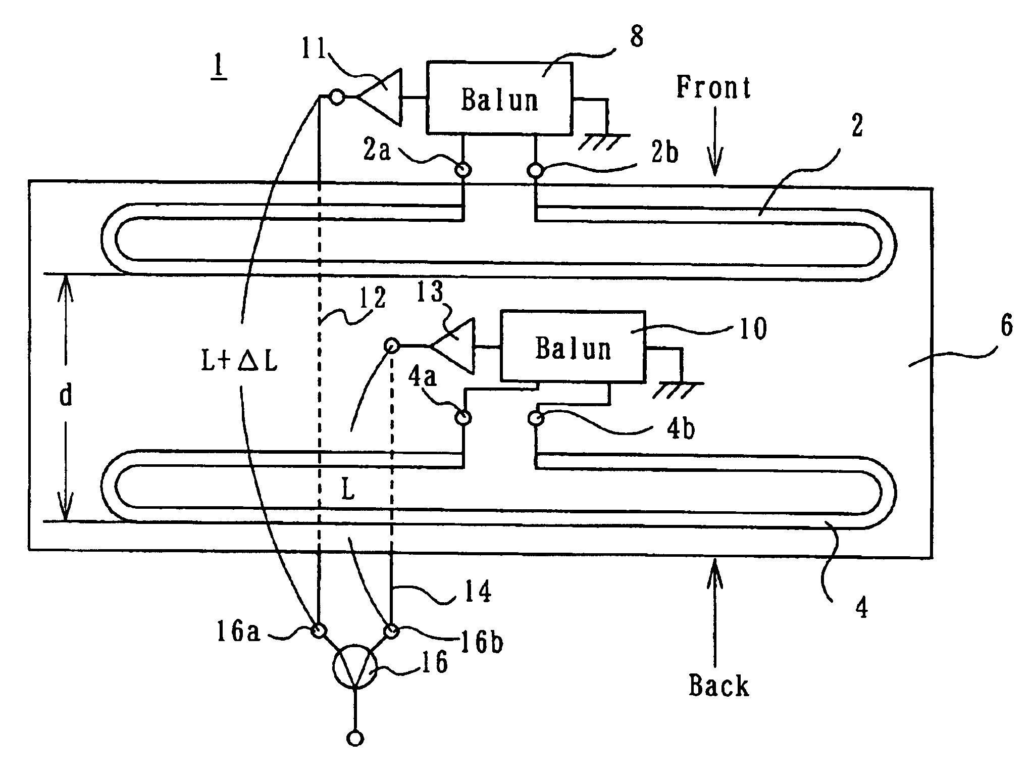
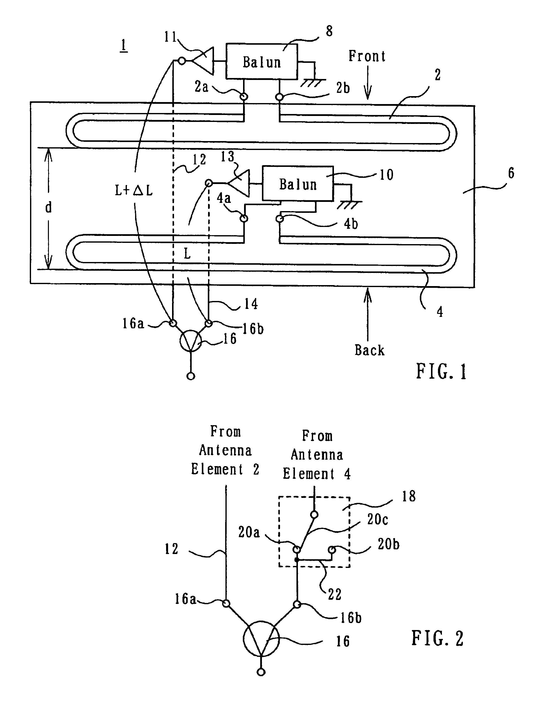
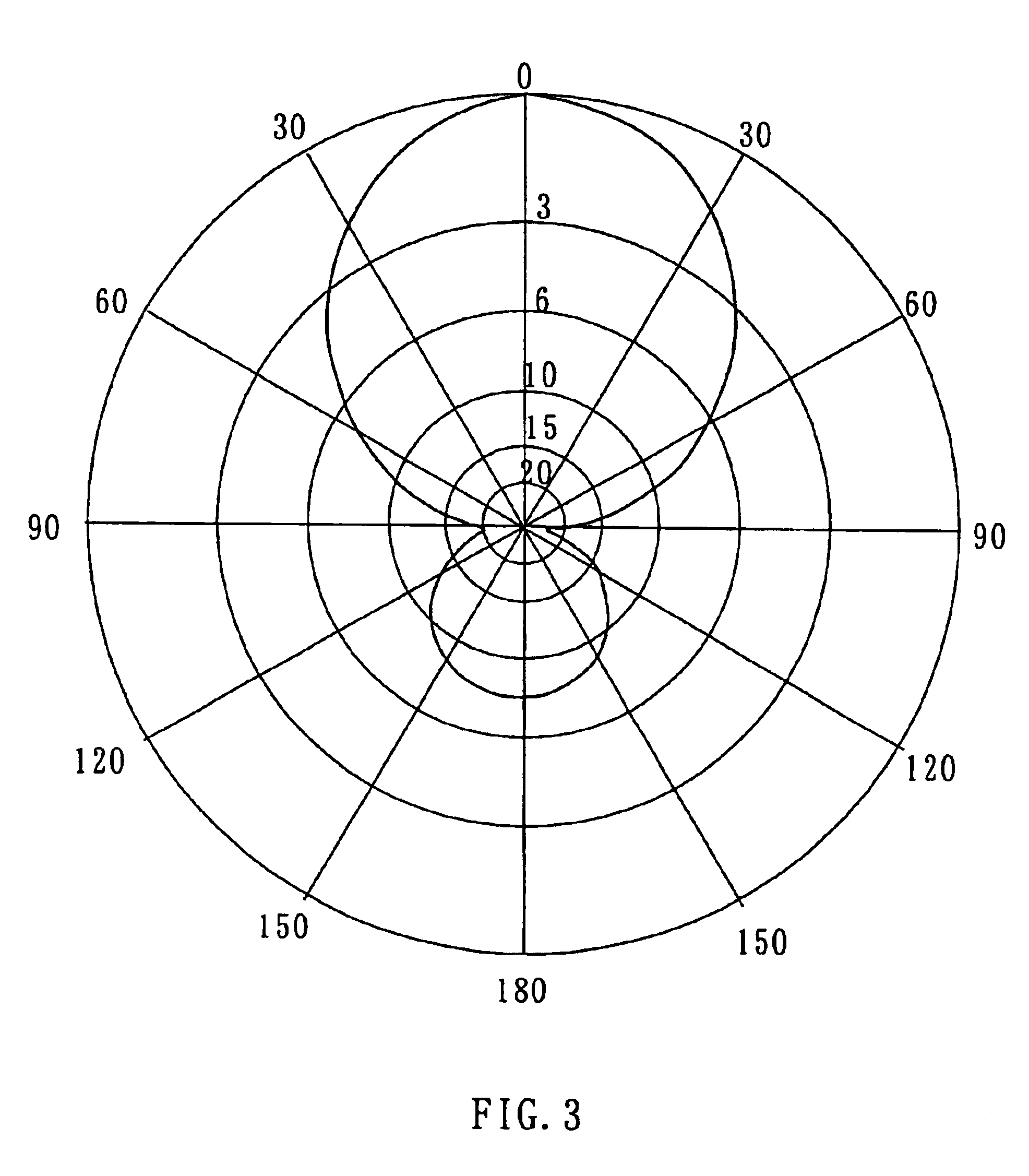
[0007]Now, let the antenna of the above-described arrangement be studied, ignoring the variable phase means. Received signals resulting from receiving a radio wave from the first direction by the first and second antenna elements are combined in the combining means. Received signals resulting from receiving a radio wave from the second direction by the first and second antenna elements have their phases inverted substantially by 180° at the input of the combining means before being combined, and, therefore, the signals resulting from the wave from the second direction received by the first and second antenna elements are cancelled out. Thus, this antenna can have an improved F / B ratio. Since the distance between at least the two antenna elements is shorter than a quarter of the wavelength of the waves employed, the antenna as a whole can be small in size. By placing the variable phase means in the first state, the antenna receives almost no radio waves from the second direction. When the variable phase means is placed in the second state, the phases of the signals resulting from the radio wave from the first direction received by the first and second antenna elements are opposite in the input of the combining means, and, therefore, the antenna receives almost no radio wave from the first direction. Thus, by selecting the first and second states of the variable phase means, the antenna can be placed in states in which it receives almost no radio waves from selected ones of the first and second directions.
[0009]Since the received signals from the respective antenna elements are combined after being amplified, the antenna can have an improved C / N ratio.
[0012]When the antenna with the above-described arrangement is to be used in, for example, the first frequency band, the switching means are opened so that only the dipole antenna elements can be used. If it is desired to use the antenna to receive radio waves in the second frequency band, the switching means are all closed so that the extension elements are connected to the associated dipole antenna elements. In this way, radio waves in the first and second different frequency bands can be received well.
[0014]Each of the first and second antennas can receive a radio wave well from a particular direction, and the two antennas are arranged such that their “particular” directions can be orthogonal. The received signals from the first and second antennas are adjusted in level by the first and second level adjusting means in such a manner that the absolute value of the combination of the received signals can be always constant and the phase can vary within a range between, for example, 0 and 180 degrees. Accordingly, any desired one of radio waves from various directions can be received well.
[0016]With the variable filter means, only a desired radio wave from one direction can be extracted by the first and second variable filters, and the extracted waves therefrom are combined. Accordingly, radio waves at other frequencies from the same direction can be rejected and give no adverse effects.

Problems solved by technology

A Yagi antenna can receive better a radio wave from a fixed, particular direction, but it cannot receive well radio waves from other directions.

Method used


Image

  • Variable directivity antenna and variable directivity antenna system using such antennas
  • Variable directivity antenna and variable directivity antenna system using such antennas
  • Variable directivity antenna and variable directivity antenna system using such antennas

Examples


first embodiment

[0036]A variable directivity antenna 1 according to the present invention may be used to receive a radio wave in a first frequency band, e.g. in the UHF band (470-890 MHz) used for television broadcasting. As shown in FIG. 1, the antenna 1 has plural, e.g. two, antenna elements 2 and 4. The antenna elements 2 and 4 are folded dipole antennas of which the entire length is, for example, about 20 cm that is equal to about one-half of the wavelength λ at the center frequency, 620 MHz, of the UHF band. The two antenna elements 2 and 4 are disposed in parallel with each other with a predetermined distance d disposed therebetween. The distance d may be, for example, 20 mm, that is equal to about λ / 20. The antenna elements 2 and 4 are planar type elements that are formed by etching a metal film on a printed circuit board 6.

[0037]Feeding points 2a and 2b disposed in the center portion of the antenna element 2 are coupled to a matching device, for example, a balun 8. Similarly, feeding points...

second embodiment

[0080]The antenna 1 shown in FIG. 1 is arranged such that the received signals from the antenna elements 2 and 4 are coupled in phase with each other to the baluns 8 and 10, that the length of the feeder 12 is longer by ΔL than the feeder 14 to provide a delay, and that the variable phase device 18 is used. Alternatively, as shown in FIG. 16, the received signal from the antenna element 2 may be coupled to the balun 8 with a phase opposite to the phase of the received signal coupled from the antenna element 4 to the balun 10, with the feeder 14 longer by ΔL than the feeder 12 used to provide a delay as represented by a delay element 150, and with the variable phase device 18 connected in the succeeding stage of the delay element 150. The same modification may be done to the variable directivity antenna shown in FIG. 6.

third embodiment

[0081]The antenna system uses two antennas 30a and 30b, but the number is not limited to two, and a larger number of antennas may be used. Furthermore, instead of using dipole antennas as the antennas 30a and 30b, folded dipole antennas as used in the antenna 1 shown in FIG. 1 may be employed.


PUM


Abstract

Folded dipole antenna elements (2, 4) are disposed generally in parallel, being spaced by a distance smaller than a quarter of the wavelength employed. The antenna elements (2, 4) are connected to a combiner (16) via feeders (12, 14) having different lengths. The difference in length between the feeders (12, 14) is such that received signals resulting from a radio wave coming to the antenna elements (2, 4) from the front and received by the antenna elements (12, 14) are in phase with each other at the inputs (16a, 16b) of the combiner (16), whereas received signals resulting from a radio wave coming to the antenna elements (2, 4) from the back and received by the antenna elements (12, 14) are 180° out of phase with each other at the inputs (16a, 16b) of the combiner (16). A variable phase device (18) is connected between one of the antenna elements (2, 4) and the combiner (16) to selectively couple the in-phase or 180° out of phase version of the received signal from that one antenna element to the combiner (16).

Description

[0001]This invention relates to a variable directivity antenna and a variable directivity antenna system using such antennas.BACKGROUND OF THE INVENTION[0002]A directional antenna may be used to receive a radio wave from a particular direction better than waves from other directions. A Yagi antenna is well-known as a directional antenna. A variable directivity antenna is used to selectively receive a desired one of radio waves from various directions. An example of variable directivity antenna is disclosed in Japanese Utility Model Publication No. SHO 63-38574 Y2 published on Oct. 12, 1988.[0003]The variable directivity antenna disclosed in this Japanese UM publication includes first and second antennas which lie to orthogonally intersect with each other in the same horizontal plane. Dipole antennas or folded dipole antennas are used as the first and second antennas. A signal received by the first antenna is applied through a first variable attenuator to a combiner, and a signal rec...

Claims


Application Information

Patent Timeline
Patent Type & Authority Patents(United States)
IPC IPC(8): H01Q9/04H01Q9/28H01Q3/26H01Q21/00H01Q1/38H01Q3/36H01Q9/26H01Q23/00H01Q25/02
CPCH01Q1/38H01Q3/36H01Q9/26H01Q23/00H01Q25/02
Inventor SHIROSAKA, TOSHIAKIFUJISAWA, SHINGO
Owner DX ANTENNA CO LTD
Learn More