Optical scanner and image reproducing apparatus

a technology of optical scanners and reproducing apparatuses, applied in the field of optical scanners and image reproducing apparatuses, can solve the problems of large motors, noise, vibration, power consumption, and difficulty in maintaining the required scan width, and achieve the effect of reducing the dot offs

Active Publication Date: 2005-08-23
RICOH KK
View PDF12 Cites 36 Cited by
  • Summary
  • Abstract
  • Description
  • Claims
  • Application Information

AI Technical Summary

Benefits of technology

[0017]Therefore, it is an object of the present invention to overcome the problems in the prior art techniques, and to provide an optical scanner and an image reproducing apparatus that include multiple optical scanning systems and a common light deflector, and that can reduce the dot offset in the fast scan direction, while providing the effective writing range and the beam detection spaces for the respective optical scanning systems.
[0019]By arranging the scan lenses of the optical scanning system to be symmetric with respect to the line passing through the rotational axis of the light deflector and extending parallel to the scanned planes of the optical scanning systems, dot offset in the fast scan direction can be reduced.
[0020]By arranging the reference reflecting positions of the optical scanning systems asymmetric with respect to the reference plane of the optical scanner, a sufficient amount of effective writing range can be maintained, while providing detection areas for the respective optical scanning systems.

Problems solved by technology

This arrangement makes it difficult to maintain the required scan width unless the area size of each reflection facet of the light deflector is increased.
However, when the reflection facet is made larger, a large-sized motor is required to rotate the light deflector.
This causes noise, vibration, power consumption, and cost to be increased.
The same problem occurs in the arrangement of increasing the rotation rate of the light deflector, causing noise, vibration, power consumption, and cost to be increased.
This also causes the above-described problems, that is, increased noise, vibration, power consumption, and cost.
Accordingly, it becomes difficult for this technique to provide the required scanning width.
Accordingly, the layout of the optical scanning systems becomes difficult.

Method used


Image

  • Optical scanner and image reproducing apparatus
  • Optical scanner and image reproducing apparatus
  • Optical scanner and image reproducing apparatus

Examples


Embodiment Construction

[0034]The preferred embodiments of the invention are described below with reference to the attached drawings.

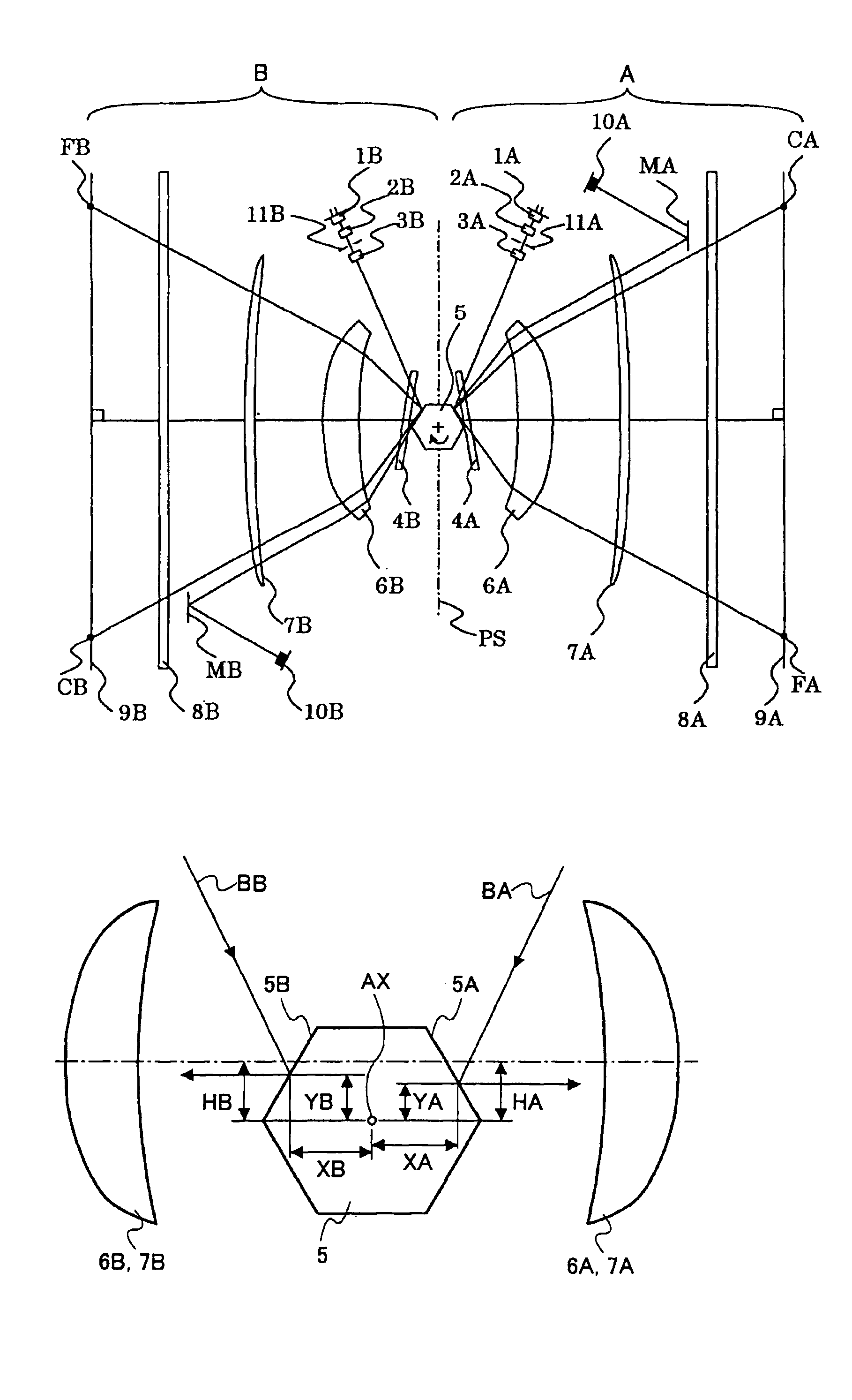
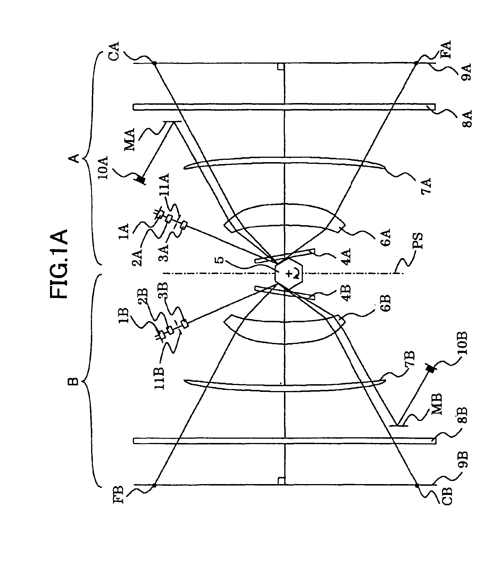
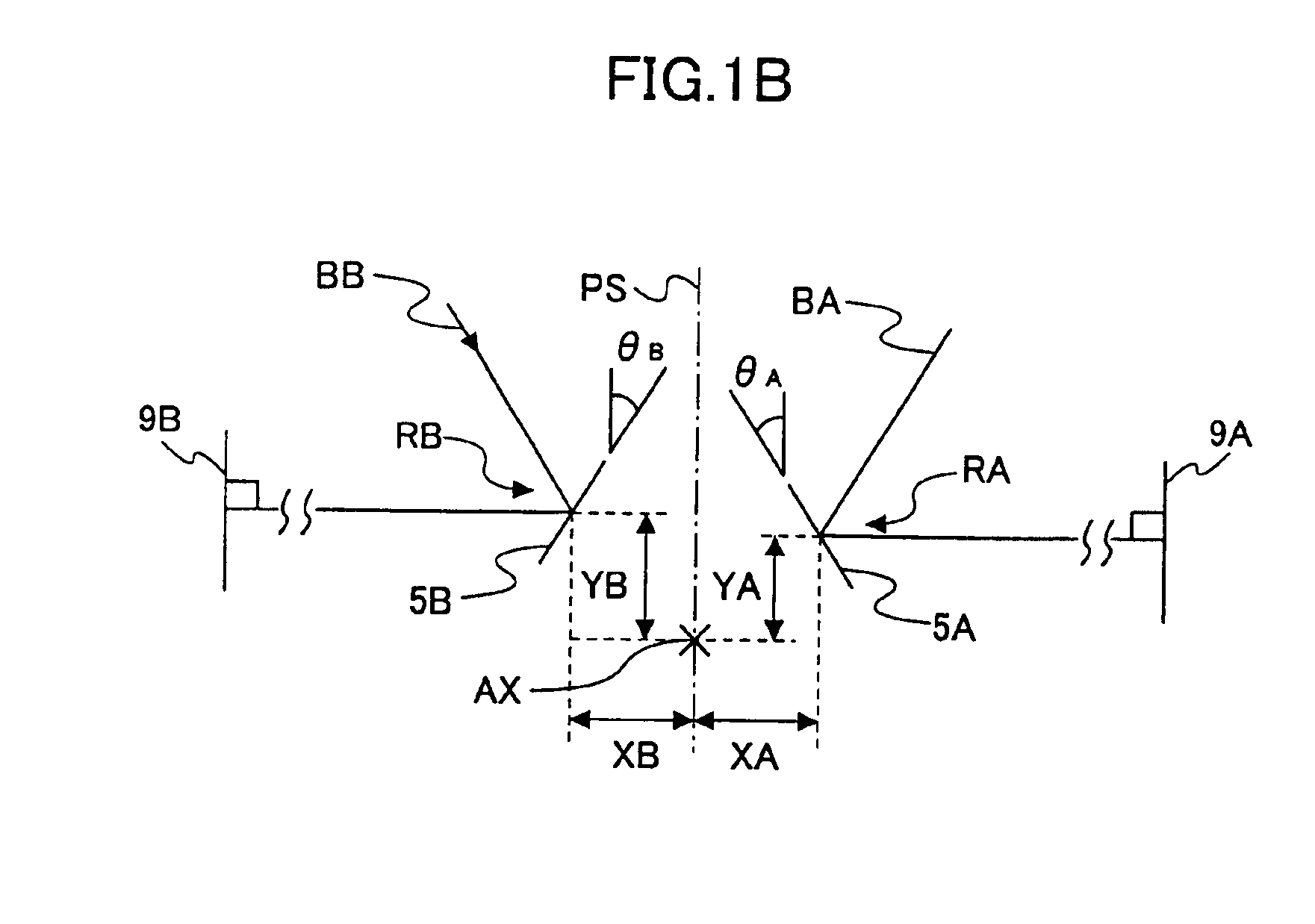
[0035]FIG. 1A illustrates a layout of the optical scanner, which is developed in a plane perpendicular to the rotational axis of the light deflector, and FIG. 1B illustrates the reflecting points on the deflecting / reflecting surfaces of the light deflector and in their vicinity.

[0036]As illustrated in FIG. 1A, the optical scanner is comprised of optical scanning systems A and B.

[0037]The optical scanner includes semiconductor lasers 1A and 1B, which are used as the light sources, coupling lenses 2A and 2B, cylindrical lenses 3A and 3B, beam-shaping apertures 11A and 11B, soundproof glass panes 4A and 4B, a light deflector 5, first scan lenses 6A and 6B, second scan lenses 7A and 7B, dust-proof glass panes 8A and 8B, scanned planes (photosensitive members) 9A and 9B, light-receiving devices (photodetectors) 10A and 10B, and mirrors MA and MB. The mirror MA and the light-receiv...


PUM


Abstract

An optical scanner includes at least a pair of optical scanning systems and a light deflector used in common between the optical scanning systems, each optical scanning system having a scan lens for guiding the beam deflected from the light deflector onto the associated scanned plane. One of the optical scanning systems has a first reference reflecting position on the light deflector, and the other optical scanning system has a second reference reflecting position on the light deflector. The first and second reference reflecting positions are asymmetric with respect to the reference plane of the optical scanner. The scan lenses of said pair of optical scanning systems are arranged to be symmetric with respect to a line passing through the rotational center of the light deflector and extending in parallel to the scanned planes.

Description

BACKGROUND OF THE INVENTION[0001]1. Field of the Invention[0002]The present invention relates to an optical scanner used in an image reproducing apparatus, such as a digital photocopy machine or a laser printer, and to an image reproducing apparatus using such an optical scanner.[0003]2. Description of the Related Art[0004]To increase the image reproduction speed in an image reproducing apparatuses, such as digital photocopy machines or laser printers, an optical scanner that has a common light deflector arranged between pairs of scanned planes in order to guide the beams onto the scanned planes located on both sides of the common deflector has been conventionally known. With such an optical scanner, optical scanning is carried out along the multiple scanned planes simultaneously. For instance, exposure can be performed simultaneously for four colors (yellow, magenta, cyan and black), and consequently, a color image can be reproduced quickly.[0005]Another type of known optical scann...

Claims


Application Information

Patent Timeline
Patent Type & Authority Patents(United States)
IPC IPC(8): G02B26/12B41J2/44G02B26/10H04N1/113
CPCG02B26/123H04N1/113
Inventor ONO, NOBUAKIHAYASHI, YOSHINORI
Owner RICOH KK
Why Eureka
Try Eureka