Digital automatic gain control

a digital automatic and gain control technology, applied in the direction of gain control, volume compression/expansion, amplitude demodulation, etc., can solve the problems of plurality of problems, myriad of problems for designers, and unsatisfactory variable gain amplifiers used in prior art agc circuits, so as to prevent input overload

a digital automatic and gain control technology, applied in the direction of gain control, volume compression/expansion, amplitude demodulation, etc., can solve the problems of plurality of problems, myriad of problems for designers, and unsatisfactory variable gain amplifiers used in prior art agc circuits, so as to prevent input overload

US6934344B2Inactive Publication Date: 2005-08-23INTERDIGITAL TECH CORP

Image

  • Digital automatic gain control
  • Digital automatic gain control
  • Digital automatic gain control

Examples


Embodiment Construction

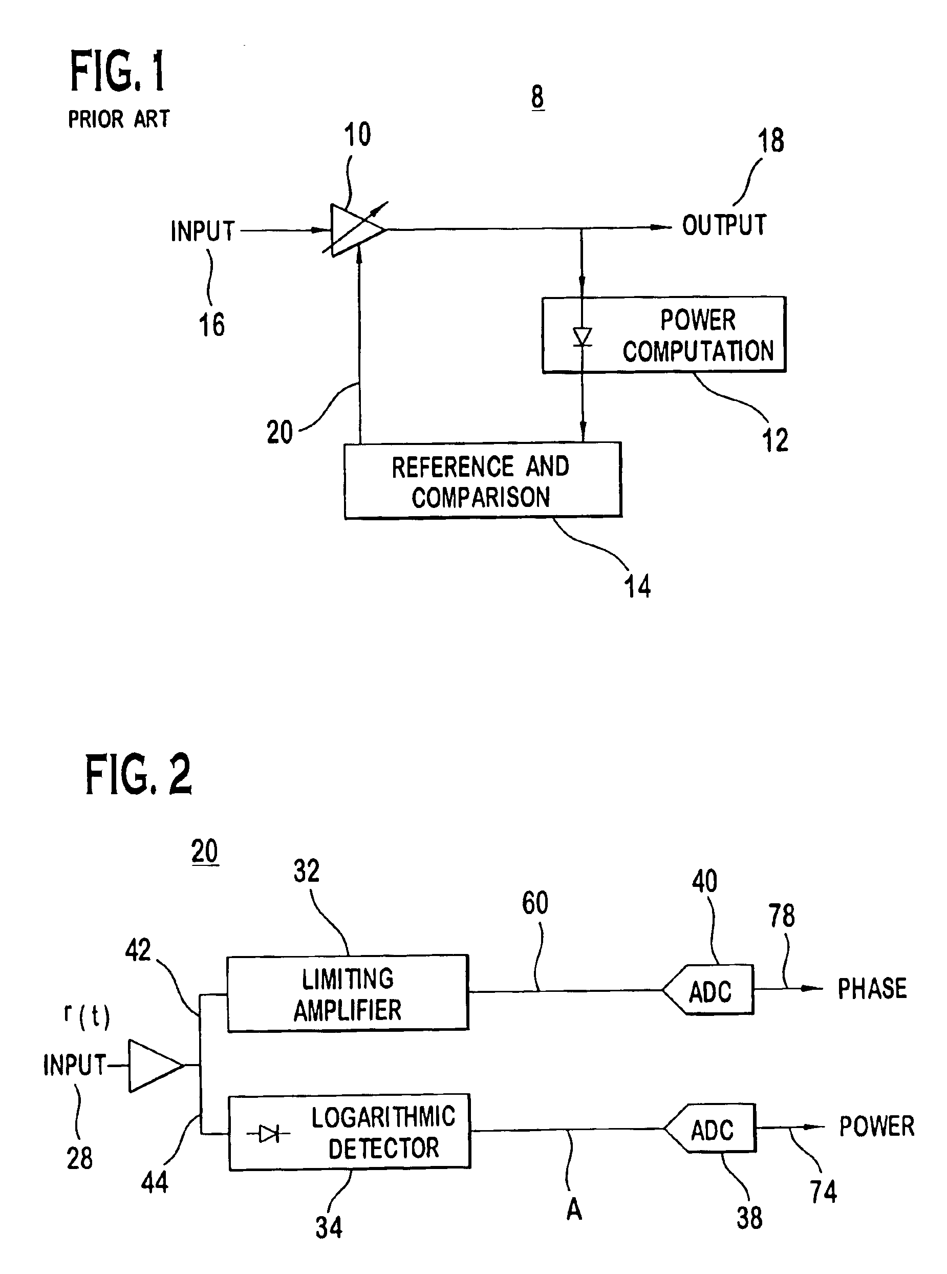
[0020]The embodiments will be described with reference to the drawing figures where like numerals represent like elements throughout.

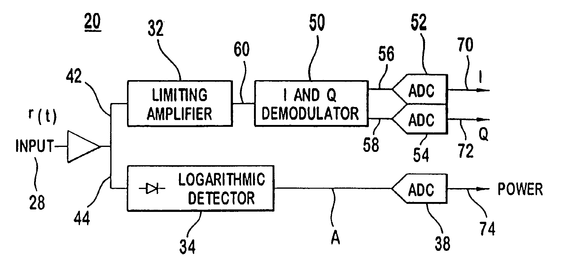
[0021]Shown in FIG. 2 is a digital automatic gain control AGC circuit 20 of the present invention. A digitally modulated signal r(t) is received from a communication channel (not shown) and is input to a receiver. One skilled in the art recognizes that additional conversion means may exist before the AGC input 28 to convert the energy used during wireless transmission to a form which is capable of being processed by the circuitry 20 of FIG. 2. Such additional conversion means are beyond the scope of this disclosure. The received, modulated signal r(t) contains amplitude and phase (frequency) information and is coupled to a limiting amplifier 32 for processing phase (frequency) components 42 and to alogarithmic detector 34 for processing amplitude components 44.

[0022]The logarithmic detector 34 has a predefined dynamic range as required for the particul...


PUM


Abstract

A system for automatic gain control prevents input overload by precisely controlling the input level of a received, digitally modulated signal without using a variable gain amplifier. A limiting amplifier in conjunction with a logarithmic detector splits an input signal path in two, providing separate phase and amplitude information for downstream digital signal processing, where the separate phase and amplitude information is processed without variable gain artifacts. The separated phase information may further be divided into I and Q signals.

Description

[0001]This application claims priority from provisional application Ser. No. 60 / 192,289, filed Mar. 27, 2000.BACKGROUND OF THE INVENTION[0002]1. Field of the Invention[0003]The present invention relates generally to wireless digital communication. More specifically, the invention relates to a system and method for controlling the gain of a received communication signal in the digital domain.[0004]2. Description of the Prior Art[0005]A digital communication system typically transmits information or data using a continuous frequency carrier with modulation techniques that vary its amplitude, frequency or phase. The information to be transmitted is input in the form of a bit stream which is mapped onto a predetermined constellation that defines the modulation scheme. The mapping of the bit stream onto a plurality of symbols is referred to as modulation. Each symbol transmitted in a symbol duration represents a unique waveform. The symbol rate or simply the rate of the system is the rat...

Claims


Application Information

Patent Timeline
23 Aug 2005
Publication
US6934344B2
IPC
H03G7/00; H03G3/30
CPC
H03G3/3052; H03G7/001
Inventors
KAZAKEVICH, LEONID; OZLUTURK, FATIH