
Centrally supported screen assembly

a central support and screen technology, applied in the direction of filtration separation, moving filter element filters, separation processes, etc., can solve the problems of affecting the quality of the screen, the screen and the basket attached thereto are shaken, and the mesh layer in the screen wears out frequently, so as to achieve convenient replacement, reduce the effect of material consumption and sufficient rigidity

Inactive Publication Date: 2005-08-30
VARCO I P INC
View PDF38 Cites 26 Cited by
  • Summary
  • Abstract
  • Description
  • Claims
  • Application Information

AI Technical Summary

Benefits of technology

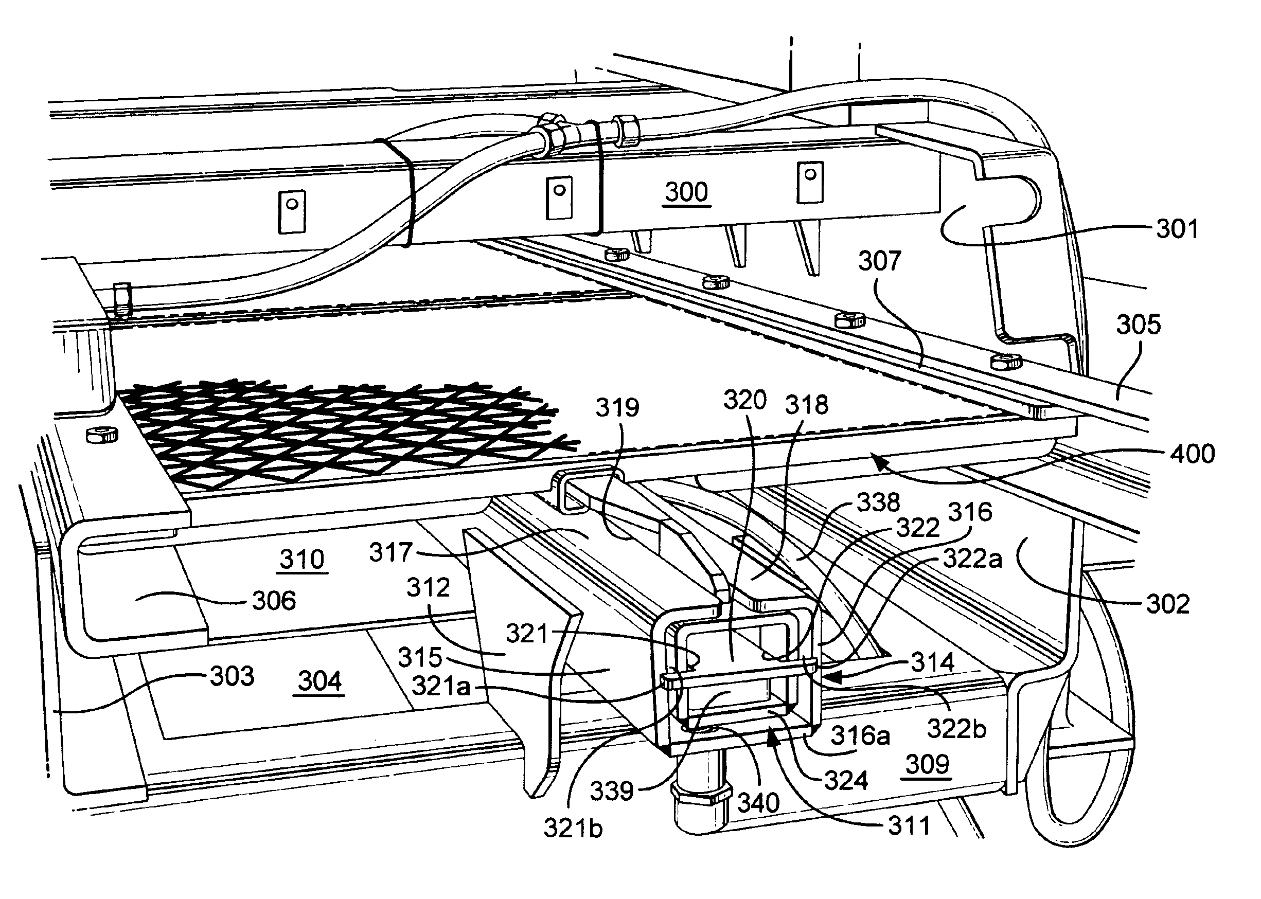
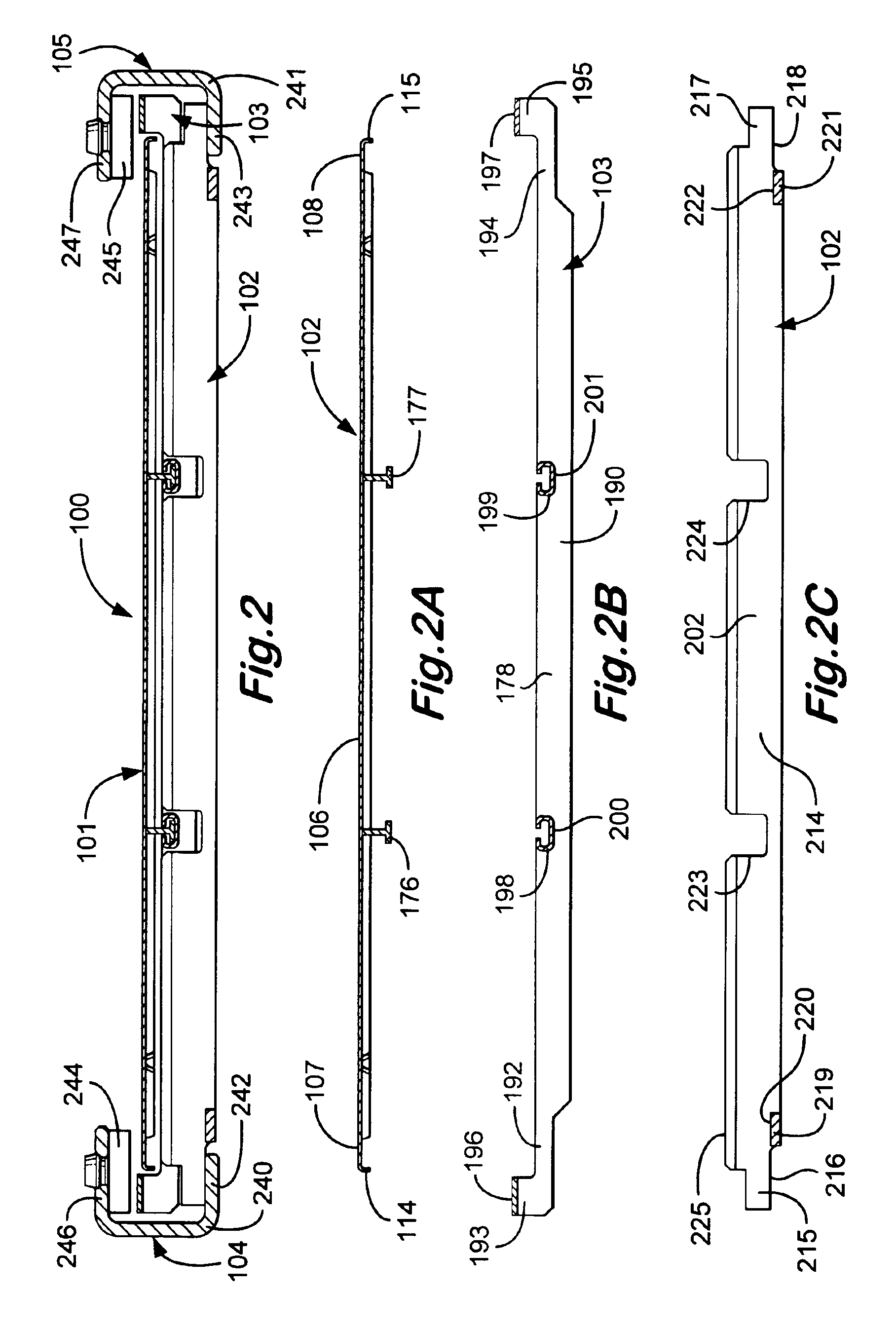
"The present invention is about a vibratory separator or shale shaker with a basket and screen assembly apparatus. The screen assembly apparatus includes one or more screens mounted in the basket. The screen assembly apparatus also includes a central support positioned beneath the screen assembly. The invention aims to provide a screen assembly that is easily replaceable and a panel for a screen that is rigid and lightweight. The invention also attempts to increase the life of the screening material and to obviate the need for mechanisms that blind areas of the screening material and decrease the screen assembly's screening capacity. The invention also provides a screen assembly that increases the screening area in a given space and makes it easier to fix the screen assembly to the shaker."

Problems solved by technology

The drilling mud often contains expensive synthetic oil-based lubricants and it is normal therefore to recover and re-use the used drilling mud, but this requires the solids to be removed from the drilling mud.
In use, the motor rotates the rotor and the offset clump weight, which causes the basket and the screens fixed thereto to shake.
The layers of mesh in the screens wears out frequently and therefore needs to be easily replaceable.
A screen of dimensions 4 feet wide by 10 feet long is difficult to handle, replace and transport.

Method used


Image

  • Centrally supported screen assembly
  • Centrally supported screen assembly
  • Centrally supported screen assembly

Examples


Embodiment Construction

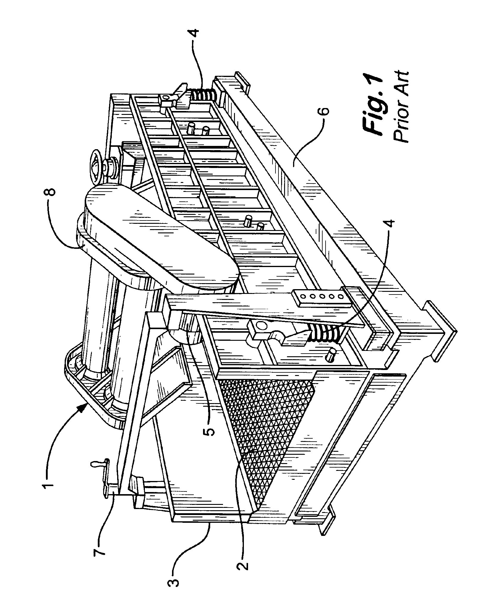
[0044]Referring to FIG. 1, a prior art shale shaker 1 is shown with a screen assembly 2 mounted therein. The screen assembly comprises a frame (not shown) and a layer of screening material tensioned over the frame. The screen assembly 2 is mounted in a basket 3, which has: an open bottom, for allowing fluid and small particles to pass into a receptacle (not shown) therebeneath; a feed end at which material to be screen is introduced (to the right of the drawing) and a mouth (to the left of the drawing) for allowing large particles to pass into a skip or ditch. The basket 3 is mounted on springs 4 (only two shown; two as shown are on the opposite side) which are supported on a structure 6. The basket 3 and the screen assembly 2 mounted therein is vibrated by a motor 5 interconnected with vibrating apparatus 8. The vibrating apparatus 8 may be of the type which comprises an unbalanced weight on the end of the motors drive shaft. Elevator apparatus 7 provides for raising and lowering o...


PUM

PropertyMeasurementUnit
sizeaaaaaaaaaa
sizeaaaaaaaaaa
lengthaaaaaaaaaa

Abstract

A vibratory separator having a basket with a first side spaced-apart from a second side, screen assembly apparatus mounted in the basket, the screen assembly apparatus having a central portion, a first screen side and a second screen side, central support apparatus connected to the basket and positioned beneath and in contact with the central portion of the screen assembly apparatus, and pressing apparatus on the first side and second side of the basket for pressing down on the first screen side and on the second screen side of the screen assembly apparatus so that the central portion of the screen assembly apparatus is higher than the first screen side and the second screen side.

Description

RELATED APPLICATIONS[0001]This is a continuation-in-part of U.S. application Ser. No. 10 / 418,743 filed 21 Apr. 2003 entitled “Vibratory Separator And Screen Assembly” naming George Alexander Burnett as inventor which is co-owned with the present invention and which is fully incorporated herein for all purposes.BACKGROUND OF THE INVENTION[0002]1. Field of the Invention[0003]The present invention relates to a vibratory separator, a screen assembly for a vibratory separator and a method for fitting a screen assembly into a vibratory separator.[0004]2. Description of Related Art[0005]In the drilling of a borehole in the construction of an oil or gas well, a drill bit is arranged on the end of a drill string and is rotated to bore the borehole. A drilling fluid or “drilling mud” is pumped through the drill string to the drill bit to lubricate the drill bit. The drilling mud is also used to carry the cuttings produced by the drill bit and other solids to the surface through an annulus for...

Claims


Application Information

Patent Timeline
Patent Type & Authority Patents(United States)
IPC IPC(8): B01D33/00B01D33/03B07B1/48B07B1/46B07BB07B1/49
CPCB01D33/0376B07B1/46B07B1/4645B07B1/4663B07B1/469B07B1/48
Inventor SEYFFERT, KENNETH W.BURNETT, GEORGE ALEXANDERMCCLUNG, III, GUY L.
Owner VARCO I P INC
Learn More