Fuel injection valve

Inactive Publication Date: 2005-08-30
HITACHI LTD +1
View PDF41 Cites 15 Cited by
  • Summary
  • Abstract
  • Description
  • Claims
  • Application Information

AI Technical Summary

Benefits of technology

[0020]In a fuel injection valve for the in-cylinder injection type engine having a fuel swirler for giving a swirling force at the upper stream of the valve sheet to the fuel passing through the surrounding area of the valve body and a nozzle injecting a swirling fuel, a fuel spray injected out from the injection port of the nozzle is so formed that the orientation of the fuel spray is deflected in a definite direction on the basis of the longitudinal axis of the fuel injection valve body, the reachable distance of the fuel spray at the deflected side is longer and the reachable distance of the fuel spray at another side opposite to the deflected side is shorter.
[0021]According to the above structure, even in case that the fuel injection valve 1 is mounted at the upper part of the cylinder 40 as shown in FIG. 6A with such an angle that the longitudinal axis C of the fuel injection valve body intersects the longitudinal axis A of the cylinder (this intersection includes three-dimensional or two-dimensional geometry), in other words, even where the fuel injection valve 1 is mounted with an angle with respect to the plane B perpendicular to the longitudinal axis A of the cylinder, the fuel spray directly injected into the cylinder 40 is still deflected toward the ignition plug 41 with respect to the longitudinal axis C of the fuel injection valve body. In addition to the deflected spray toward the ignition plug as described above, the reachable distance L1 of the spray deflected toward the ignition plug is made larger and the

Problems solved by technology

Though the basic concept of this gasoline engine was born in many years ago, there have remained many problems to be solved such as high-pressure injection technology, pressure tightness and heat resistance in order to implement those engines for injecting fuels directly into the combu

Method used


Image

  • Fuel injection valve
  • Fuel injection valve
  • Fuel injection valve

Examples


Example

[0050]Preferred embodiments of the present invention will be described by referring to the drawings.

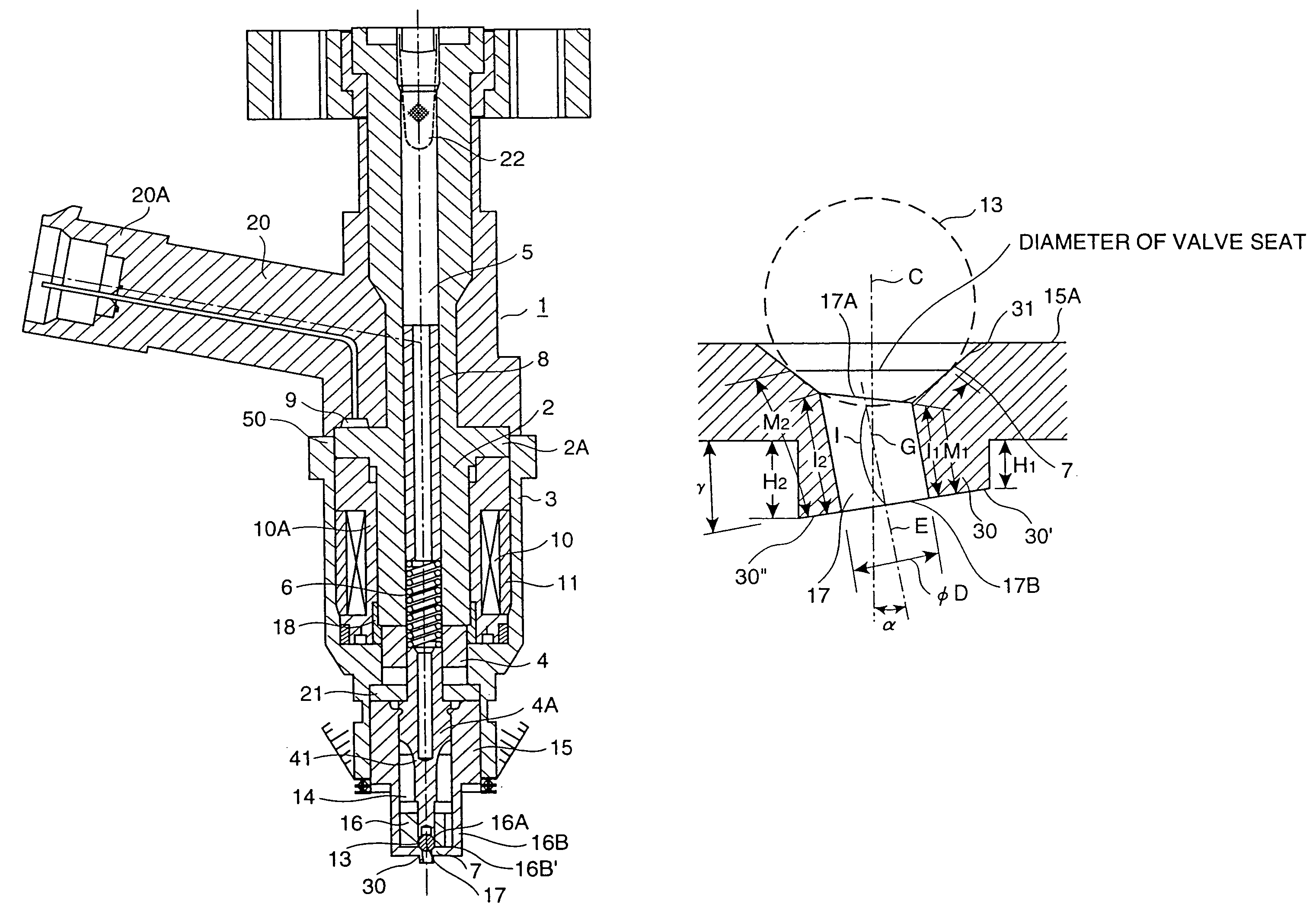
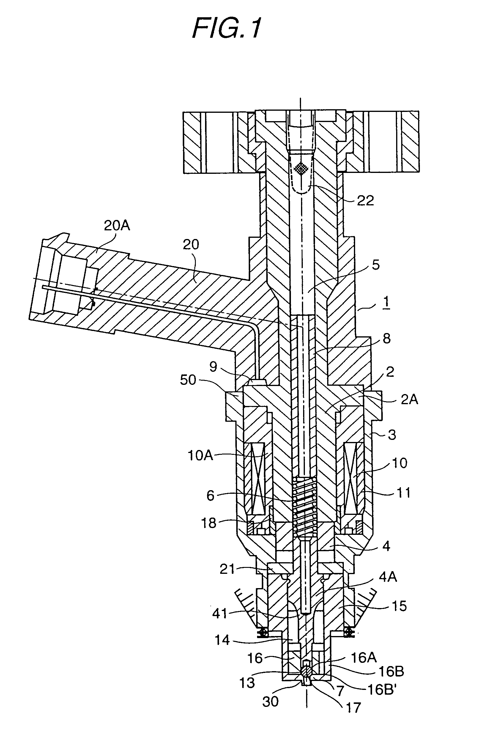
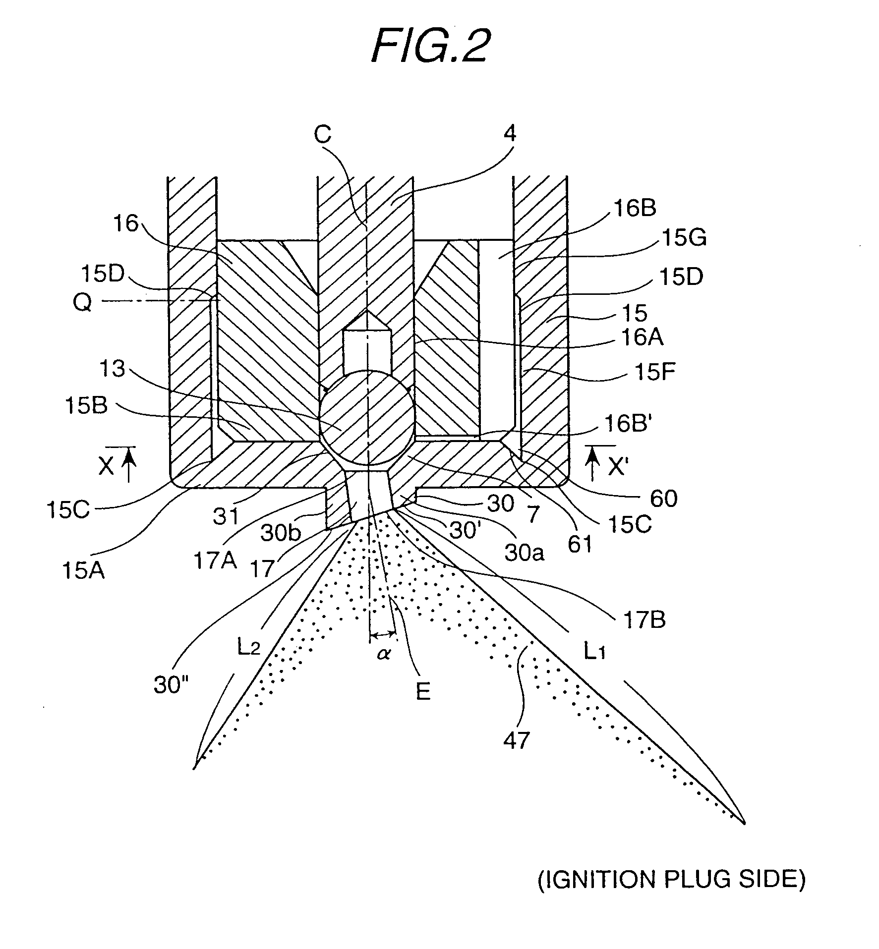
[0051]Related to one embodiment of the present invention, FIG. 1 is a vertical cross-section view of the fuel injection valve used in the in-cylinder type engine (gasoline engine), FIG. 2 is an explanatory drawing showing the injection state of the fuel spray as a magnified view of the nozzle part in FIG. 1, FIG. 3A is a vertical cross-section view of the nozzle body used in the fuel injection valve shown in FIG. 1, FIG. 3B is a bottom view of the nozzle body, FIG. 4 is a partially magnified view showing the valve sheet part and the neighborhood of the fuel injection port shown in FIG. 3A, and FIG. 5 is a horizontal cross-section view of the swirl orifice provided inside the nozzle body viewed from the line X–X′ in FIG. 2.

[0052]The fuel injection valve 1 shown in FIG. 1 is an example of the fuel injection valve using a magnet coil used as an actuator. As magnetic circuit components fo...


PUM


Abstract

A fuel swirling means 15 for giving a swirling force at the upper stream of the valve sheet 7 to the fuel passing through the surrounding area of the valve body 13 and a nozzle 16 injecting a swirling fuel are provided. A fuel spray 47 injected out from the injection port 17 of the nozzle 16 is so formed that the orientation of the fuel spray is deflected in a definite direction on the basis of the longitudinal axis C of the fuel injection valve body, the reachable distance L1 of the fuel spray at the deflected side is longer and the reachable distance L2 of the fuel spray at another side opposite to the deflected side is shorter.

Description

[0001]This application is a continuation of application Ser. No. 09 / 199,456, filed Nov. 25, 1998.BACKGROUND OF THE INVENTION[0002]The present invention relates to a fuel injection valve (injector) for the gas direct injection type engine in which fuel is injected directly into the cylinder of the engine.[0003]As for the gasoline engine satisfying such social needs as high power, high fuel-efficiency and low pollution, engines using fuel injection valves of gas direct injection type (gas direct injection type gasoline engine) are remarked. Though the basic concept of this gasoline engine was born in many years ago, there have remained many problems to be solved such as high-pressure injection technology, pressure tightness and heat resistance in order to implement those engines for injecting fuels directly into the combustion chamber, however, the state-of-the-art in technology enables mass-production by today's advances in control technology and production technology, and thus, the ...

Claims


Application Information

Patent Timeline
IPC IPC(8): B05B1/34F02M61/00F02M59/00F02M63/00F02M39/00F02M61/16F02M61/18
CPCB05B1/3431F02M61/162F02M61/168F02M61/18F02M61/1806F02M61/188F02M61/165Y10S239/90
Inventor SHIBATA, KOJINAMAIZAWA, YASUOSEKINE, ATSUSHISASAKI, YUICHIISHIKAWA, TOHRU
Owner HITACHI LTD
Why Eureka
Try Eureka