Optical recording medium, and method and device using the same

a technology of optical recording medium and optical recording medium, which is applied in the field of optical recording medium, can solve the problems of insufficient recording sensitivity, and achieve the effect of less dependent on the wavelength of semiconductor lasers

Inactive Publication Date: 2005-08-30
RICOH KK +1
View PDF146 Cites 6 Cited by
  • Summary
  • Abstract
  • Description
  • Claims
  • Application Information

AI Technical Summary

Problems solved by technology

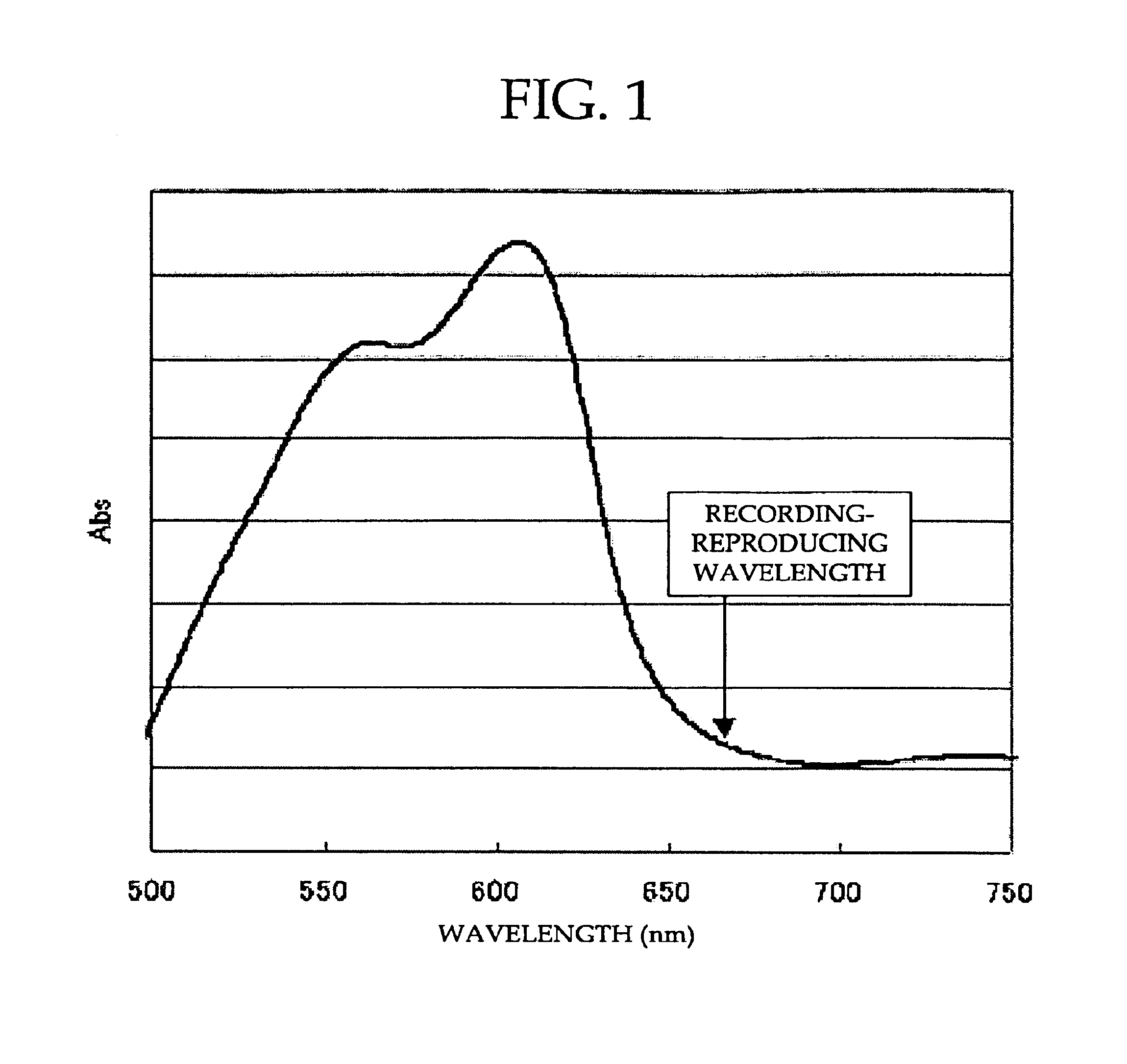
In particular, the oscillation wavelength shifts to a longer wavelength at high temperatures, thus inviting a decreased extinction coefficient “k” of the dye material used in the recording layer and leading to an insufficient recording sensitivity.

Method used


Image

  • Optical recording medium, and method and device using the same
  • Optical recording medium, and method and device using the same
  • Optical recording medium, and method and device using the same

Examples


example 1

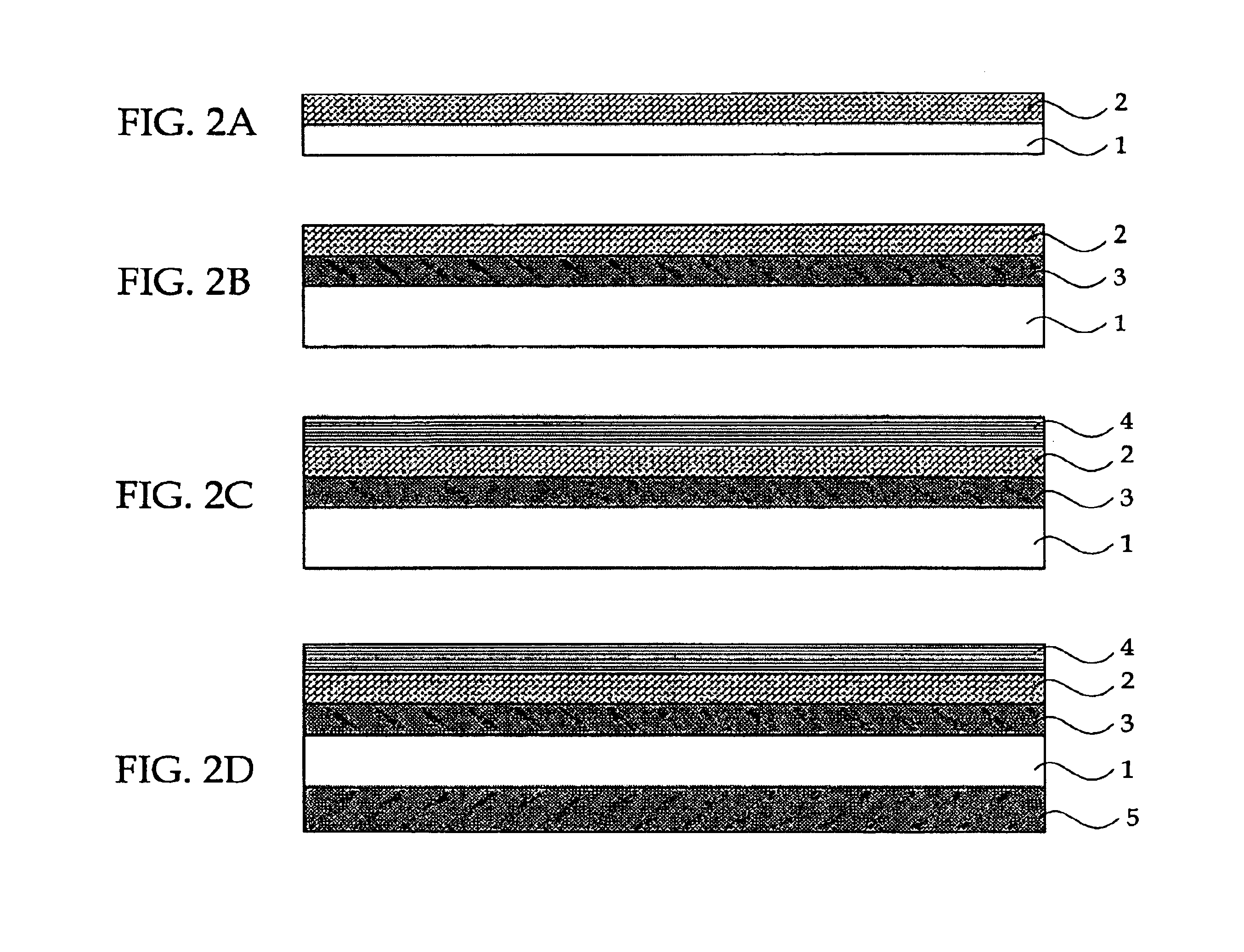
[0190]A coating composition was prepared by dissolving a mixture of Compounds A-9, B-4 and C-4 in proportions shown in Table 8 in 2,2,3,3-tetrafluoropropanol. The coating composition was applied to a polycarbonate substrate by spin coating to form an organic dye layer 100 nm (1000 angstroms) thick. The polycarbonate substrate was prepared by injection molding, had a thickness of 0.6 mm and carried guide-grooves having a depth of 175 nm (1750 angstroms), a half width of 0.25 μm and a track pitch of 0.74 μm. Then, a gold reflective layer 130 nm (1300 angstroms) thick was formed on the organic dye layer by sputtering, followed by formation of a protective layer of an acrylic photopolymer 5 μm thick thereon. Another injection-molded polycarbonate substrate 0.6 mm thick was bonded to the protective layer using an acrylic photopolymer to thereby yield an optical recording medium.

examples 2 to 10

[0191]A series of optical recording media was prepared by the procedure of Example 1, except for using dyes shown in Table 8.


PUM

PropertyMeasurementUnit
wavelengthaaaaaaaaaa
refractive indexaaaaaaaaaa

Abstract

An optical recording medium includes a substrate and at least a recording layer deposited on or above the substrate, and the recording layer contains at least one formazan-metal chelate compound containing a formazan compound and a metal component; at least one squarylium-metal chelate compound containing a squarylium compound and a metal component; and at least one diarylamine compound.

Description

BACKGROUND OF THE INVENTION[0001]1. Field of the Invention[0002]The present invention relates to an optical recording medium, as well as an optical recording method and an optical recording device using the optical recording medium.[0003]2. Description of the Related Art[0004]Recordable DVD media have been developed as next-generation optical disks with large capacities. The possibilities of increasing the recording capacity of the DVD media are in the development of a recording material that can minimize a recording pit to be formed, introduction of image compression technologies such as Moving Picture Experts Group-2 (MPEG 2), and improvement in the method of shortening the wavelength of the semiconductor laser used to read the recording pit.[0005]An AlGaInP semiconductor laser with a wavelength of 670 nm is only one red semiconductor laser that has been developed and commercialized for a bar code reader and a measuring instrument. Along with the development of the optical discs w...

Claims


Application Information

Patent Timeline
Patent Type & Authority Patents(United States)
IPC IPC(8): B32B3/02B32B5/16B41M5/26G11B7/24C09B53/00C09B23/00C09B57/00C09B50/00C09B50/06C09B50/10C09B67/22G11B7/24035G11B7/24073G11B7/24079G11B7/24085G11B7/244G11B7/249G11B7/2542G11B7/2548
CPCC09B67/0034G11B7/246G11B7/2467G11B7/249Y10T428/21G11B7/2463G11B7/247G11B7/248G11B7/2531G11B7/2532G11B7/2533G11B7/2534G11B7/2542G11B7/2548G11B7/256G11B7/2585G11B7/259G11B7/2595G11B2007/24612G11B2007/25417G11B7/245
Inventor NOGUCHI, SOHSATO, TSUTOMUTOMURA, TATSUYAUENO, YASUNOBUSHIMIZU, IKUOKINUGASA, MOTOHARUTOYODA, HIROSHI
Owner RICOH KK
Why Eureka
Try Eureka