
Polarization-stabilized all-optical switch

Active Publication Date: 2005-08-30
MASSACHUSETTS INST OF TECH
View PDF4 Cites 5 Cited by
  • Summary
  • Abstract
  • Description
  • Claims
  • Application Information

AI Technical Summary

Benefits of technology

[0008]In brief overview, the present invention relates to an all-optical switch that is significantly insensitive to polarization instabilities in the switch and, consequently, does not require active polarization control. The optical switc

Problems solved by technology

The electronic signal bandwidth limitations incurred during the O / E conversion and the conversion back to an optical signal (E / O conversion), however, often result in router congestion and reduced data throughput.
In addition, the low energy optical pulses received at the router after propagation over long distances can be degraded, for example, by chromatic dispersion and nonlinear effects in the transmission fiber.
Optical switches utilizing nonlinearities in optical fibers are subject to polarization instability due to temperature variations and acoustic disturbances.
Semiconductor materials are used as the nonlinear media in some optical switches, however, the operational speed of these switches is typically limited by multiple physical processes.
For example, long-lasting refractive index nonlinearities cause performance degradations that are dependent on the data statistics and the data rate.

Method used


Image

  • Polarization-stabilized all-optical switch
  • Polarization-stabilized all-optical switch
  • Polarization-stabilized all-optical switch

Examples


Embodiment Construction

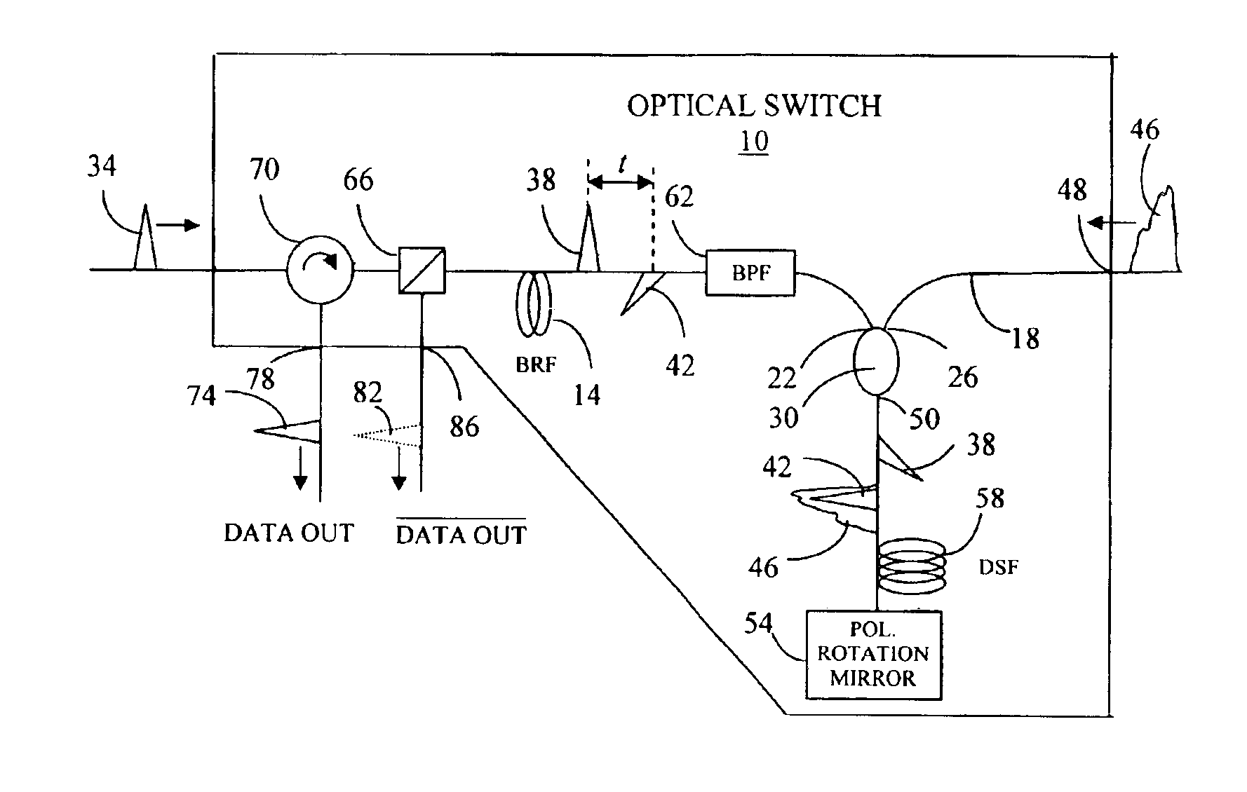
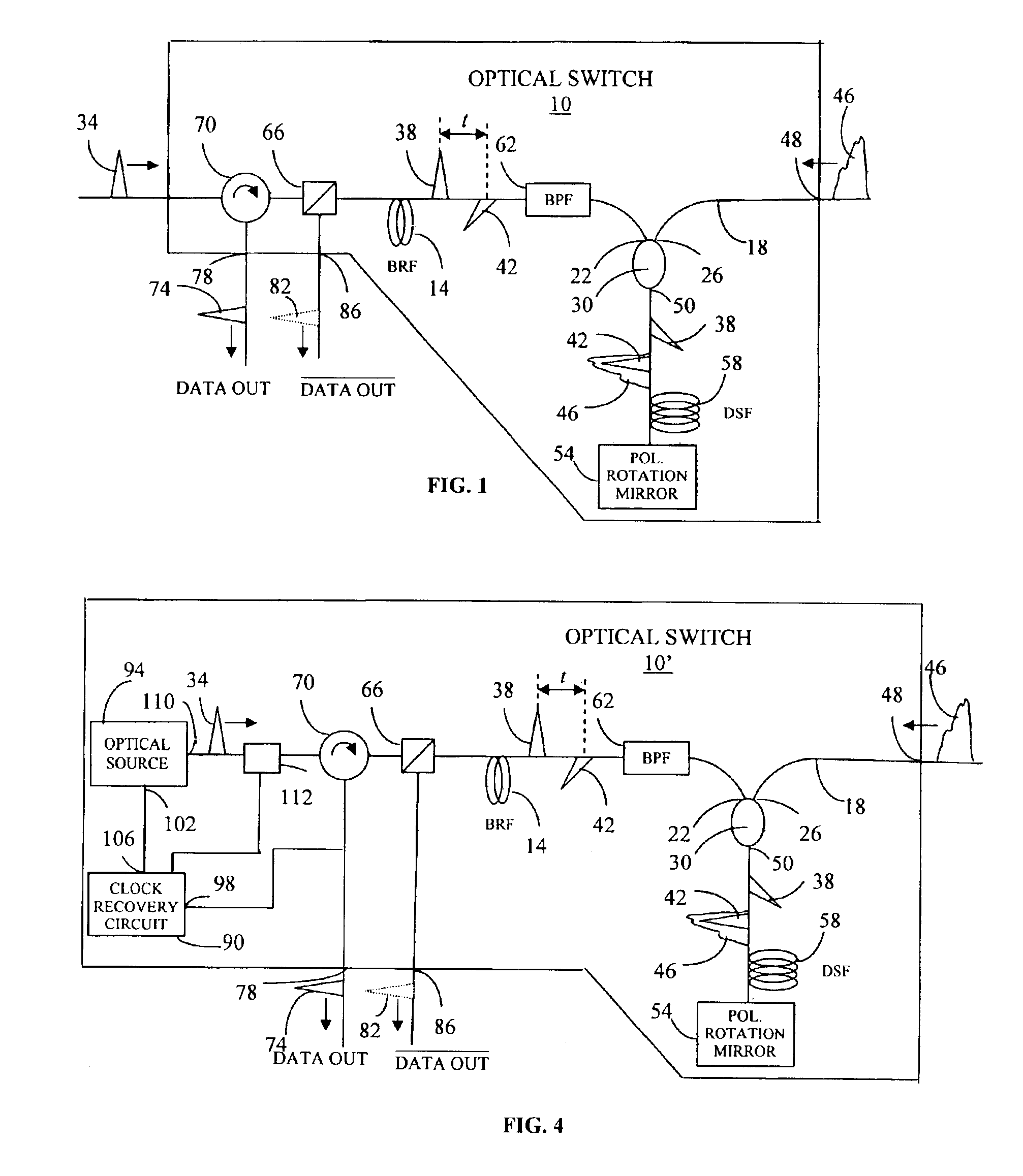
[0026]FIG. 1 illustrates an all-optical switch 10 constructed in accordance with the present invention. The switch 10 is configured as a folded ultrafast nonlinear interferometer (FUNI). The switch 10 is a component of an all-optical 3R regenerator that re-amplifies, re-shapes and re-times optical data pulses. Reshaping removes distortion in an optical data pulse caused, for example, by chromatic dispersion and nonlinear properties of the transmission path. Re-timing removes any timing jitter (i.e., variation in pulse position within a bit interval) present in an optical data pulse stream. Effectively, the regenerator recovers the clock of the data pulse stream and generates a stream of local clock pulses to match the data pulse clock. The all-optical switch 10 outputs a local transform-limited optical clock pulse if an optical data pulse is present in the corresponding bit interval of the data pulse stream. Conversely, no local optical clock pulse is output if the optical data puls...


PUM


Abstract

Described is an all-optical switch that is significantly insensitive to polarization instabilities. The optical switch can be configured as an ultrafast logic gate, a switch for ultrafast communication systems or a key component of an all-optical regenerator. Performance is independent of the statistical characteristics of the data controlling the switch. The switch includes a birefringent optical channel in communication with one end of a nonlinear optical channel through a coupler and a polarization rotation mirror in communication with the other end of the nonlinear channel. An optical data pulse for controlling the switching function is provided to one port of the coupler.

Description

CROSS REFERENCE TO RELATED APPLICATIONS[0001]This application claims priority to provisional U.S. patent application Ser. No. 60 / 378,746, filed May 8, 2002, titled “Polarization Stabilized All-Optical Switch,” the entirety of which provisional application is incorporated by reference herein.GOVERNMENT RIGHTS IN THE INVENTION[0002]This invention was made with United States government support under Contract No. F19628-00-C-002 awarded by the Defense Advanced Research Project Agency (DARPA). The government may have certain rights in the invention.FIELD OF THE INVENTION[0003]The invention relates generally to optical switches. More specifically, the invention relates to devices and methods for regeneration and switching in high data rate optical communication systems.BACKGROUND[0004]Typical optical networks are based on high-speed electronic routers interconnected by optical fiber links utilizing wavelength division multiplexing (WDM) transmission systems. To achieve packet routing, the...

Claims


Application Information

Patent Timeline
IPC IPC(8): G02F1/35H04Q11/00H04J14/06H04J14/08
CPCG02F1/3515H04Q11/0005G02F1/3517H04J14/06H04J14/08H04Q2011/0035H04Q2011/0041
Inventor ROBINSON, BRYAN S.SAVAGE, SHELBY J.HAMILTON, SCOTT A.IPPEN, ERICH P.
Owner MASSACHUSETTS INST OF TECH
Learn More