
Grease supply confirming device and method

Inactive Publication Date: 2005-09-06
NSK LTD
View PDF33 Cites 3 Cited by
  • Summary
  • Abstract
  • Description
  • Claims
  • Application Information

AI Technical Summary

Benefits of technology

[0008]The invention has been worked out under these circumstances. An aim of the invention is to provide a grease supply confirming device and method which can monitor almost always that the supply of grease into the bearing is certainly effected and thus rapidly detect any abnormality in the supply of grease.
[0017]In this arrangement, it is made possible to always monitor to see whether or not a grease is certainly supplied into the bearing. Thus, any abnormality in the supply of grease can be rapidly detected, making it possible to prevent the seizing of the bearing remarkably. Accordingly, the life of the bearing which operates grease-lubricated at a high rotary speed can be prolonged. Further, it is not necessary that the operation of the bearing be visually monitored, making it possible to reduce the burden on users and the cost, including labor cost.
[0019]Further, the movable body may be a metal body supported in the piping and the detecting member may be an eddy current type displacement sensor. In this arrangement, the position of the movable body in the grease can be accurately seized.

Problems solved by technology

Thus, when the bearing continues to operate at a high rotary speed without the supply of grease, the grease is deteriorated, causing the seizing of the bearing soon.
In practice, it has been difficult to monitor visually the bearing of spindle for machine tool which operates continuously for a long period of time for the state of grease supply because cost, including labor cost, rises.
In actuality, the state of grease supply can be visually confirmed only several times a day, making it impossible to early detect abnormalities such as suspension of supply of grease by the supplier.
It has been still disadvantageous in that when the machine tools operate at a rotary speed as high as greater than dmN 1,500,000, the bearing undergoes seizing, making the spindle out of order.

Method used


Image

  • Grease supply confirming device and method
  • Grease supply confirming device and method
  • Grease supply confirming device and method

Examples


Embodiment Construction

[0023]Embodiments of implementation of the invention will be described in detail in connection with the attached drawings.

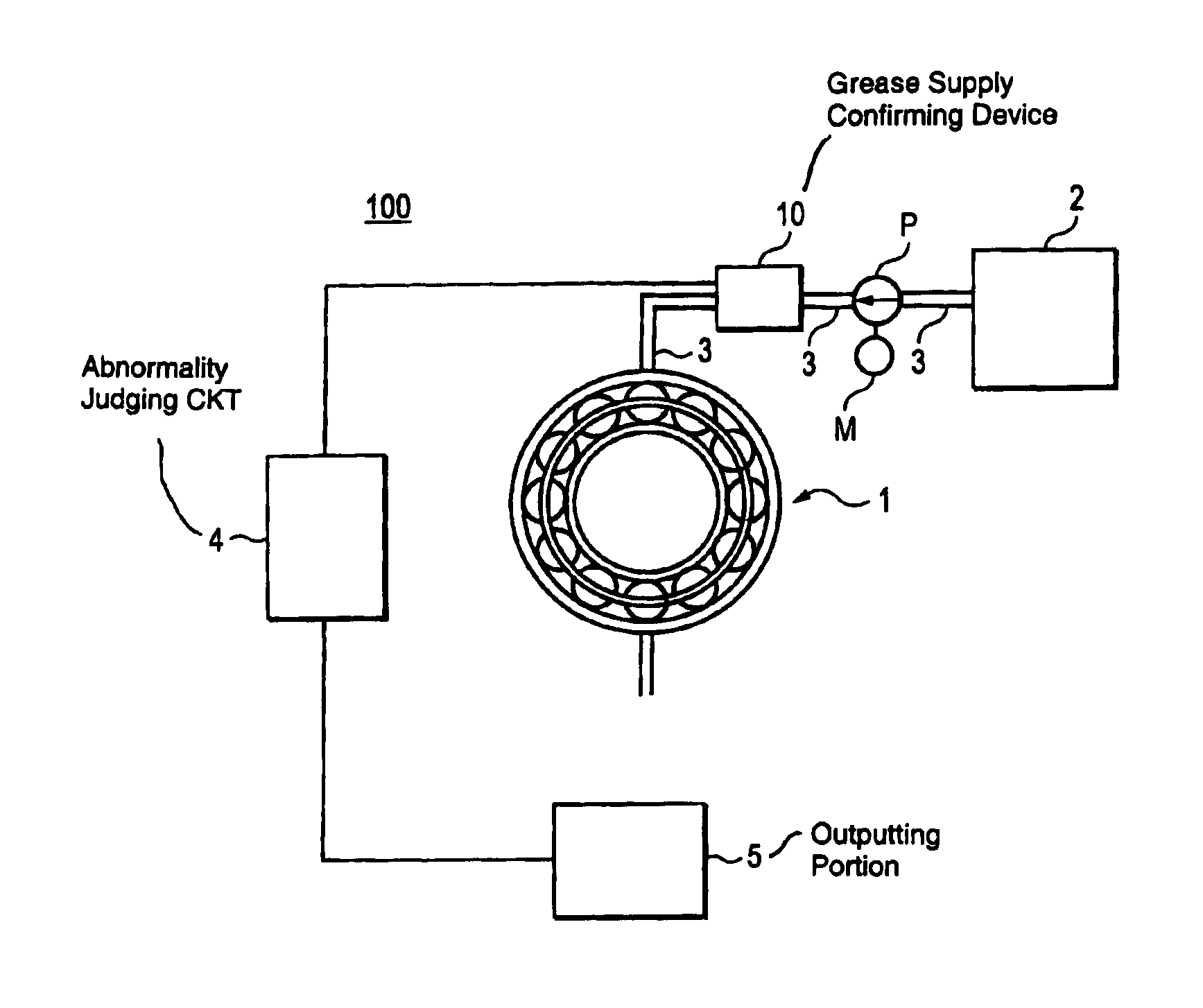
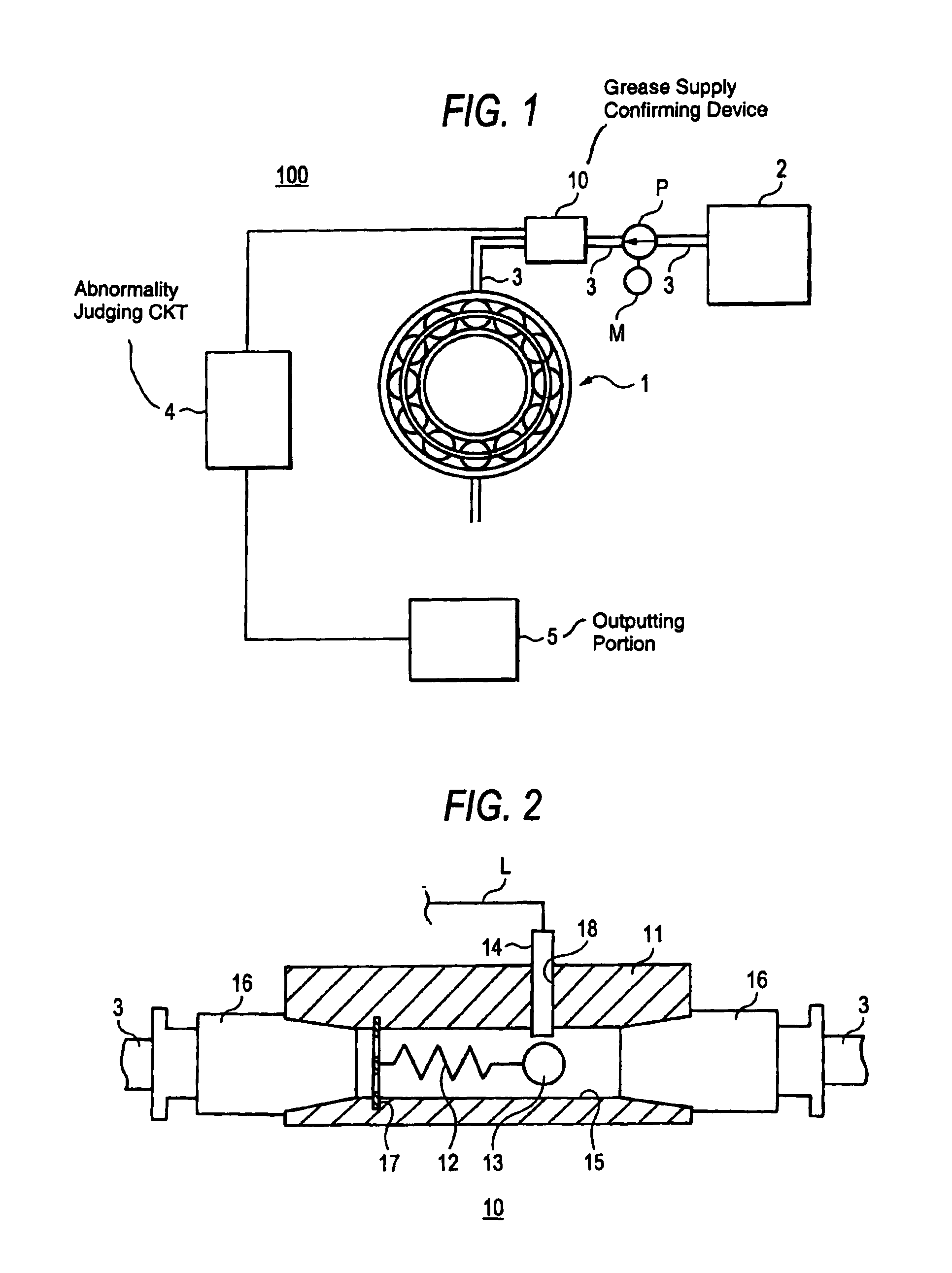
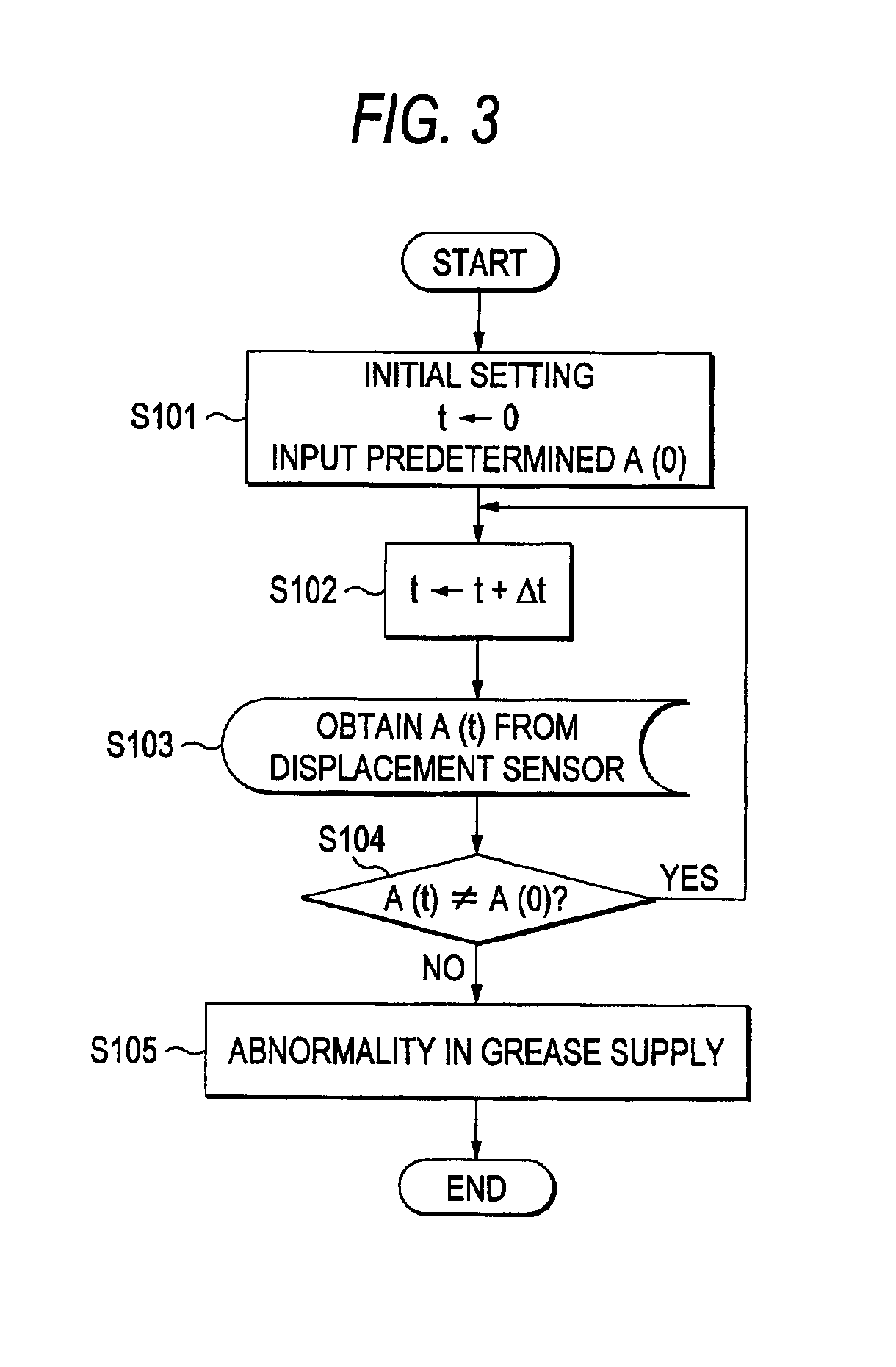
[0024]FIG. 1 illustrates a grease supplying mechanism 100 comprising a grease supply confirming device 10 as an embodiment of implementation of the invention. The grease supplying mechanism 100 comprises a bearing portion 1, a grease tank 2, a feed pipe 3, a motor M, and a grease supply confirming device 10. The bearing portion 1 rotatably supports a spindle (not shown). The grease tank 2 reserves a grease. The pump P pumps a grease from the grease tank 2 into the bearing portion 1 through the feed pipe 3 that connects between the bearing portion 1 and the pump P. The motor M drives the pump P. The grease supply confirming device 10 confirms the supply of the grease into the bearing portion 1 and is provided at the feed pipe 3. Connected To the grease supply confirming device 10 is an abnormality judging circuit 4 to which an outputting portion 5 is connected. Bo...


PUM


Abstract

A grease supply confirming device confirming the supply of a grease into a bearing, according to the present invention includes a detecting member an elastic supporting member and a movable body. The movable body such as a metal spherical body is movably provided in a piping through which a grease to be supplied flows. The elastic supporting member is provided in the piping for supporting the movable body. The detecting member such as an eddy current type displacement sensor detects to see whether or not the grease is supplied in accordance with the displacement of the movable body. The grease supply confirming device further includes an abnormality judging circuit connected to the detecting member for judging the abnormality in grease supply, and an outputting portion for outputting an alarm according to the instruction from the abnormality judging circuit.

Description

BACKGROUND OF THE INVENTION[0001]The present invention relates to a grease supply confirming device and method which can be applied to bearings for use in, e.g., spindle for machine tools that are required to operate at a high rotary speed and have a prolonged life.[0002]Most bearings for the spindle for machine tools and bearings for spindle devices are grease-lubricated for cost reduction or omission of maintenance. In order to meet the requirements for higher productivity, the spindle of machine tools must operate at higher rotary speed. Thus, these bearings have been required to operate at higher rotary speed.[0003]The upper limit of rotary speed of grease-lubricated rolling bearing devices is dmN1,500,000 (dm: pitch diameter (mm); N: shaft rotary speed (rpm)) at maximum.[0004]In order to prevent seizing of bearings, it has been proposed to use a grease supplying device.[0005]In the case where such a grease supplying device is used, it is important to confirm to see whether or n...

Claims


Application Information

Patent Timeline
IPC IPC(8): F16N29/00F16N29/04F16C33/66F16N7/38
CPCF16N29/04
Inventor YAKURA, KENJI
Owner NSK LTD
Learn More