Quick change adaptor for rotary machines
- Summary
- Abstract
- Description
- Claims
- Application Information
AI Technical Summary
Benefits of technology
Problems solved by technology
Method used
Image
Examples
Embodiment Construction
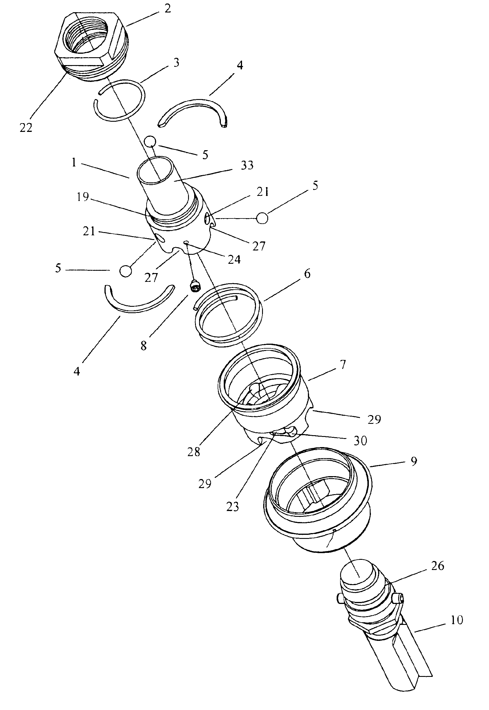
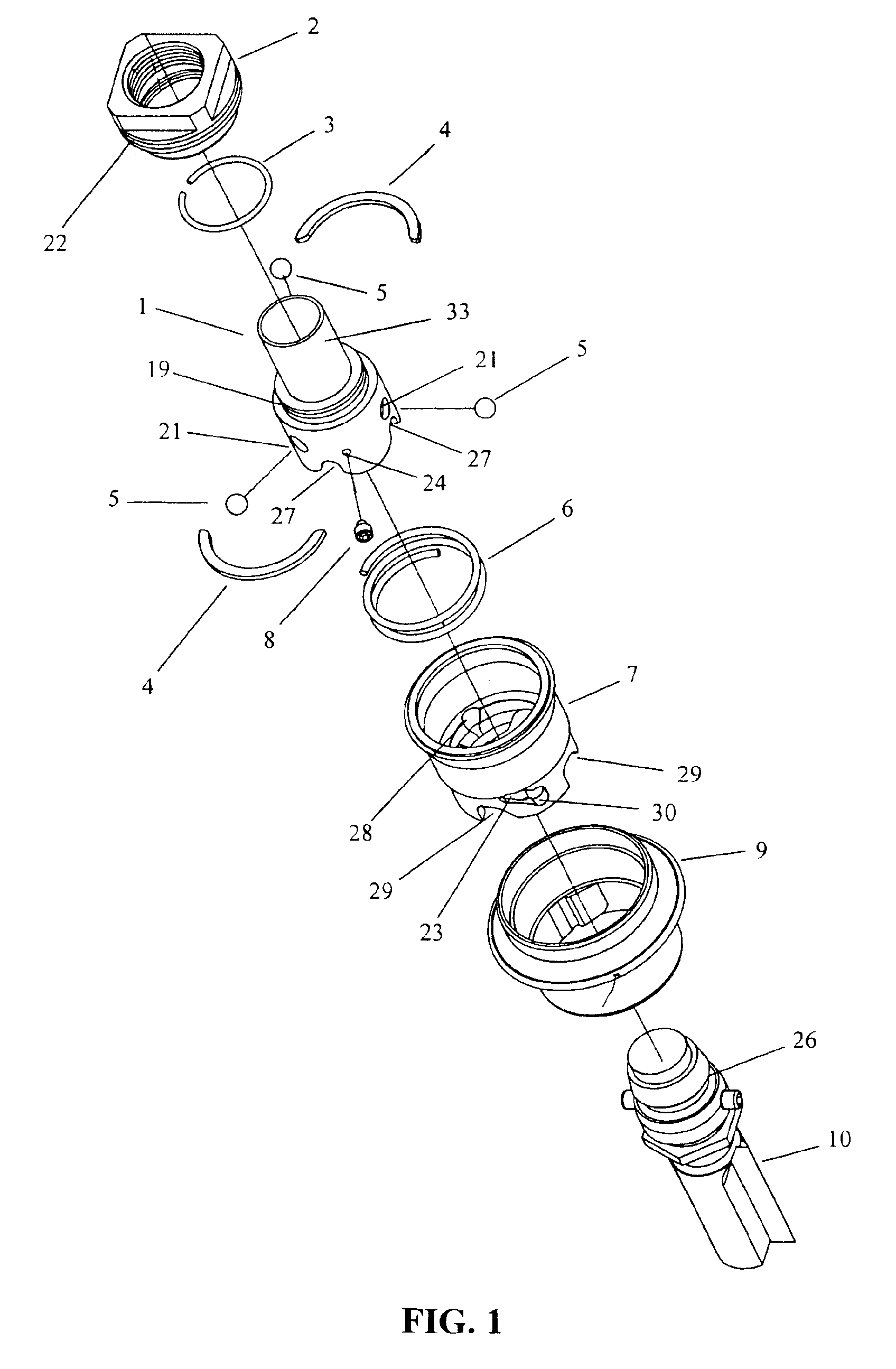
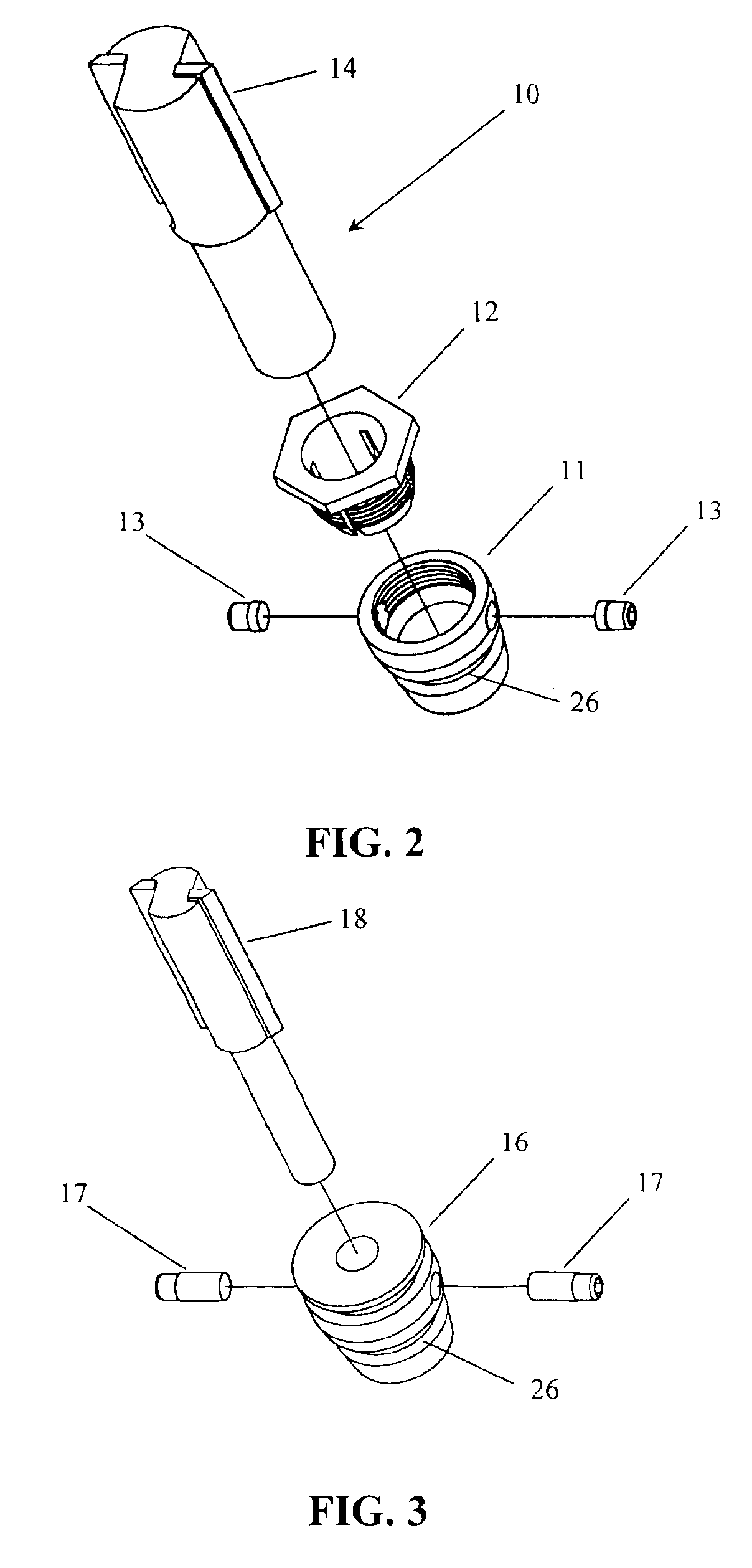
[0019]Referring to FIG. 1, shown is a quick-change assembly in accordance with one embodiment of the present invention. As shown in FIG. 1, the assembly includes a quick-change body (1), a quick-change body adaptor nut (2), a QC body adaptor nut retaining ring (3), two force compensation half rings (4), locking balls (5), an actuating spring (6), an actuating collar (7), an actuating collar cam pin (8), an actuating collar shroud (9), and a bit adaptor assembly (10) which, in this embodiment may be an adaptor for a ½″ bit.
[0020]In forming the QC assembly, the QC body adaptor nut retaining ring (3) may be inserted into a retaining ring groove (19) on the quick-change body (1), and the quick-change body adaptor nut (2) may be slipped down onto the body (1) and snapped over the ring (3). In this embodiment an internal groove (20) (shown in FIG. 4) in the quick-change body adaptor nut (2) captures the retaining ring (3) and may prevent the nut (2) from being separated from the body (1) ...
PUM
| Property | Measurement | Unit |
|---|---|---|
| Size | aaaaa | aaaaa |
| Torque | aaaaa | aaaaa |
Abstract
Description
Claims
Application Information
 - R&D
- Intellectual Property
- Life Sciences
- Materials
- Tech Scout
- Unparalleled Data Quality
- Higher Quality Content
- 60% Fewer Hallucinations
Browse by: Latest US Patents, China's latest patents, Technical Efficacy Thesaurus, Application Domain, Technology Topic, Popular Technical Reports.
© 2025 PatSnap. All rights reserved.Legal|Privacy policy|Modern Slavery Act Transparency Statement|Sitemap|About US| Contact US: help@patsnap.com


